System configuration
Multi−master system
10
Networking via PROFIBUS−DP
10.2
10.2.3
L
10.2−2
EDSPM−TXXX−9.0−11/2009
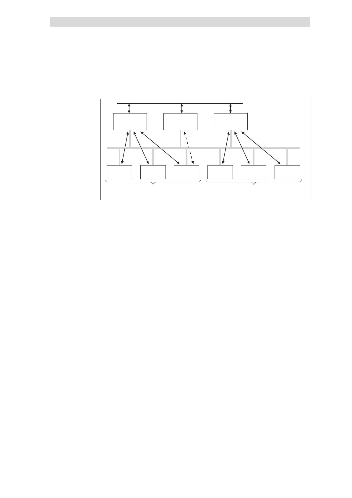
10.2.3 Multi−master system
Token
Master 1
(DPM 1)
Master 3
(DPM 1)
Master 2
(DPM 2)
Slave 1 Slave 2 Slave 3 Slave 4 Slave 5 Slave 6
01
2
epm−t226
Fig. 10.2−2 PROFIBUS−DP multi−master system
Subsystem consisting of master 1 and slaves 1 ... 3 with cyclic data transfer.
Subsystem consisting of master 3 and slaves 4 ... 6 with cyclic data transfer.
For configuration and diagnostics, master 2 can communicate with slave 1 ... 6.
The data transfer is acyclic.
In multi−master operation, several masters are connected to one bus. They either
form independent subsystems consisting of one class 1 master (DPM 1) each and
the corresponding slaves, or additional class 2 masters (DPM 2) for configuration
and diagnostics. The input and output images of the slaves can be read by all
masters. Only the respective class 1 master (DPM 1) can write the outputs.
 Loading...