Parameterising 2/4xcounter module
Encoder (modes 1, 3, and 5)
12
Parameter setting via system bus (CAN) / CANopen
12.4
12.4.4
L
12.4−11
EDSPM−TXXX−9.0−11/2009
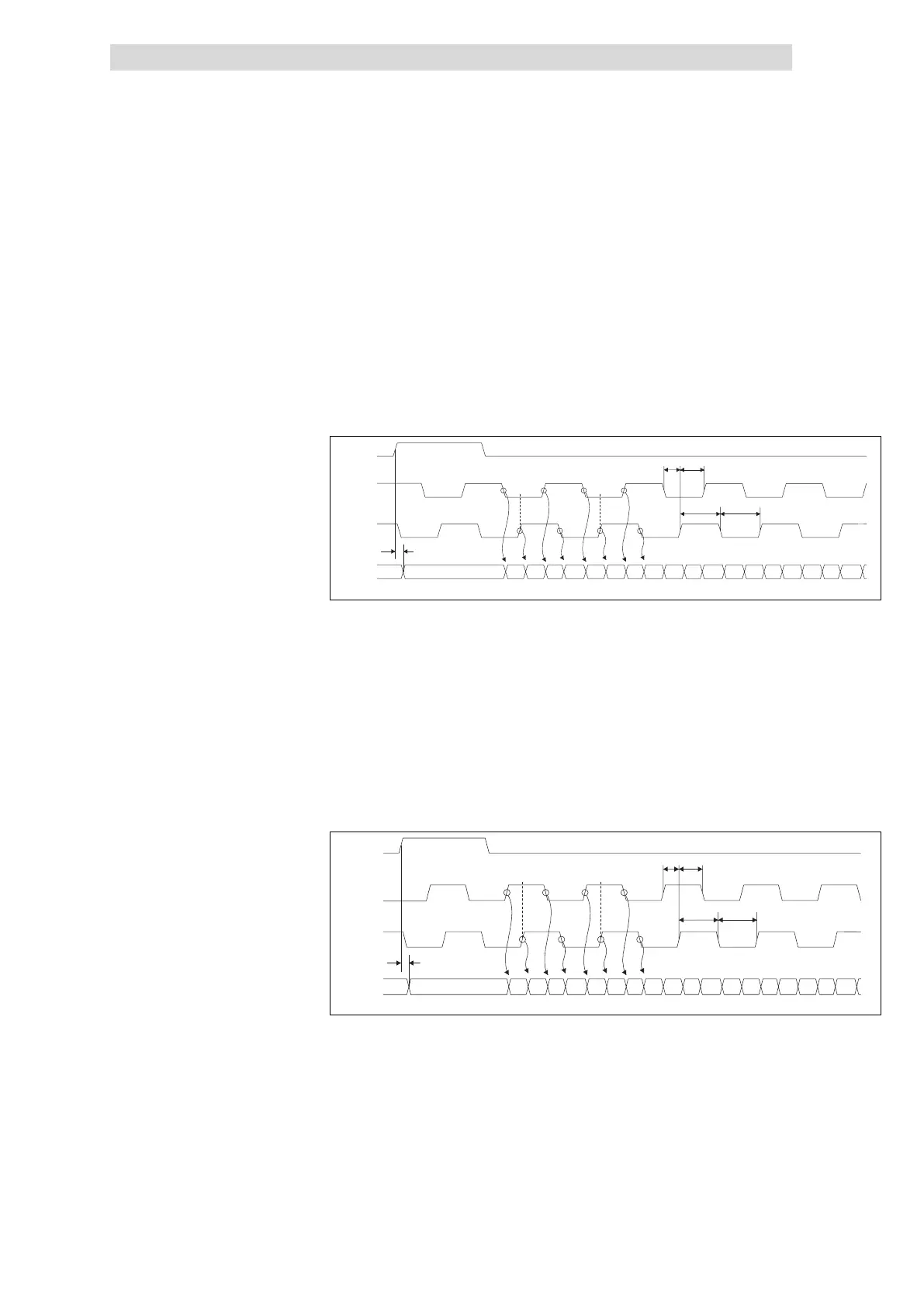
The counter is incremented by 1 on
l a LOW−HIGH edge at input IN2 / IN5 (A) and a LOW level at the input
IN3 / IN6 (B).
l a HIGH−LOW edge at input IN2 / IN5 (A) and a HIGH level at input
IN3 / IN6 (B).
l a LOW−HIGH edge at input IN2 / IN5 (A) and a HIGH level at input
IN3 / IN6 (B).
l a HIGH−LOW edge at input IN2 / IN5 (A) and a LOW level at the input
IN3 / IN6 (B).
RES
B
A
Counter
00000000XXXX
TreH2d
TcIH
TdL2cIH Tc IH2dH
TcIL
01 02 03 04 05 06 07 08 09 0A 0B 0C 0D 0E 0F 10 11 12
epm−t073
Fig. 12.4−14 Signal characteristic of 2/4xcounter in the mode 5 (upcounter)
The counter is decremented by 1 on
l a LOW−HIGH edge at input IN2 / IN5 (A) and a HIGH level at input
IN3 / IN6 (B).
l a HIGH−LOW edge at input IN2 / IN5 (A) and a LOW level at the input
IN3 / IN6 (B).
l a LOW−HIGH edge at input IN2 / IN5 (A) and a LOW level at the input
IN3 / IN6 (B).
l a HIGH−LOW edge at input IN2 / IN5 (A) and a HIGH level at input
IN3 / IN6 (B).
RES
B
A
Counter
00000000 FF FE FD FC FB FA F9 F8F8XXXX
TreH2d
F7 F6 F5 F4
TclL
TclH2dHTdL2clH
TclH
F3 F2 F1 F0 EF EE
epm−t074
Fig. 12.4−15 Signal characteristic of 2/4xcounter in the mode 5 (downcounter)
Signal characteristic in mode 5
 Loading...