16×digital output 0.5A
4
The modular system
4.8
L
4.8−2
EDSPM−TXXX−9.0−11/2009
DO 16xDC24V 0.5A
EPM – T225 0.5A
1
2.0
3.1
4.2
L+
5.3
6.4
7.5
8.6
9.7
10.0
11.1
12.2
13.3
14.4
15.5
16.6
17.7
F
18
1
3
0
2
1
2
3
4
14
15
16
17
18
.
Z
Z
Z
Z
Z
Z
Z
–
+
DC 24 V
(DC 18
…35V)
epm−t126 epm−t122
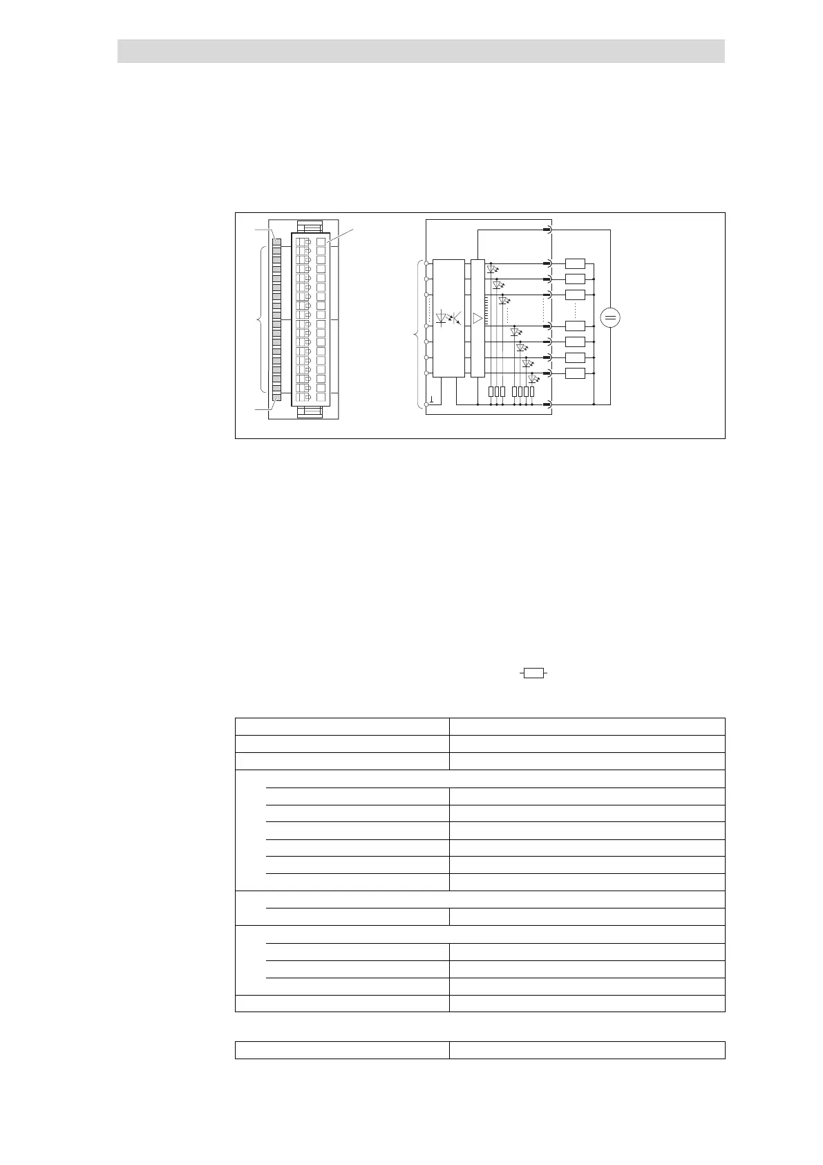
Fig. 4.8−2 Front view and connection of 16×digital output 0.5A
Status display L+; LED (yellow) is lit
when a supply voltage is applied
Terminal strip assignment
details
1 DC 24 V supply voltage
2 Digital output A.0
2 ×Status display .0 ... .7; LED
(green) is lit when the corresponding
output is triggered
3 Digital output A.1
4 Digital output A.2
5 Digital output A.3
Status display F; LED (red) is lit in
case of overload, overheating or
short circuit
... ...
15 Digital output A.13
16 Digital output A.14
17 Digital output A.15
18 GND (reference potential)
Connection to backplane bus
Z
Load
Type
16×digital output 0.5A
Voltage supply DC 5 V / 80 mA (via backplane bus)
Connectable cable cross−section £ 1.5 mm
2
(³ AWG 16)
Digital output data
Rated load voltage DC 24 V (DC 18 ... 35 V)
Number of outputs 16
Max. output current per output 0.5 A (sustained short−circuit−proof)
Max. output summation current 5A
Delay time < 1 ms
Electrical isolation from backplane bus Yes, via optocouplers
Communication
Output data 2 bytes
Dimensions
Width 25.4 mm
Height 76.0 mm
Depth 76.0 mm
Weight 50 g
Order designation EPM−T225
Status display and terminal
assignment
Technical data
 Loading...