3-phase mains c
onnecon 480 V
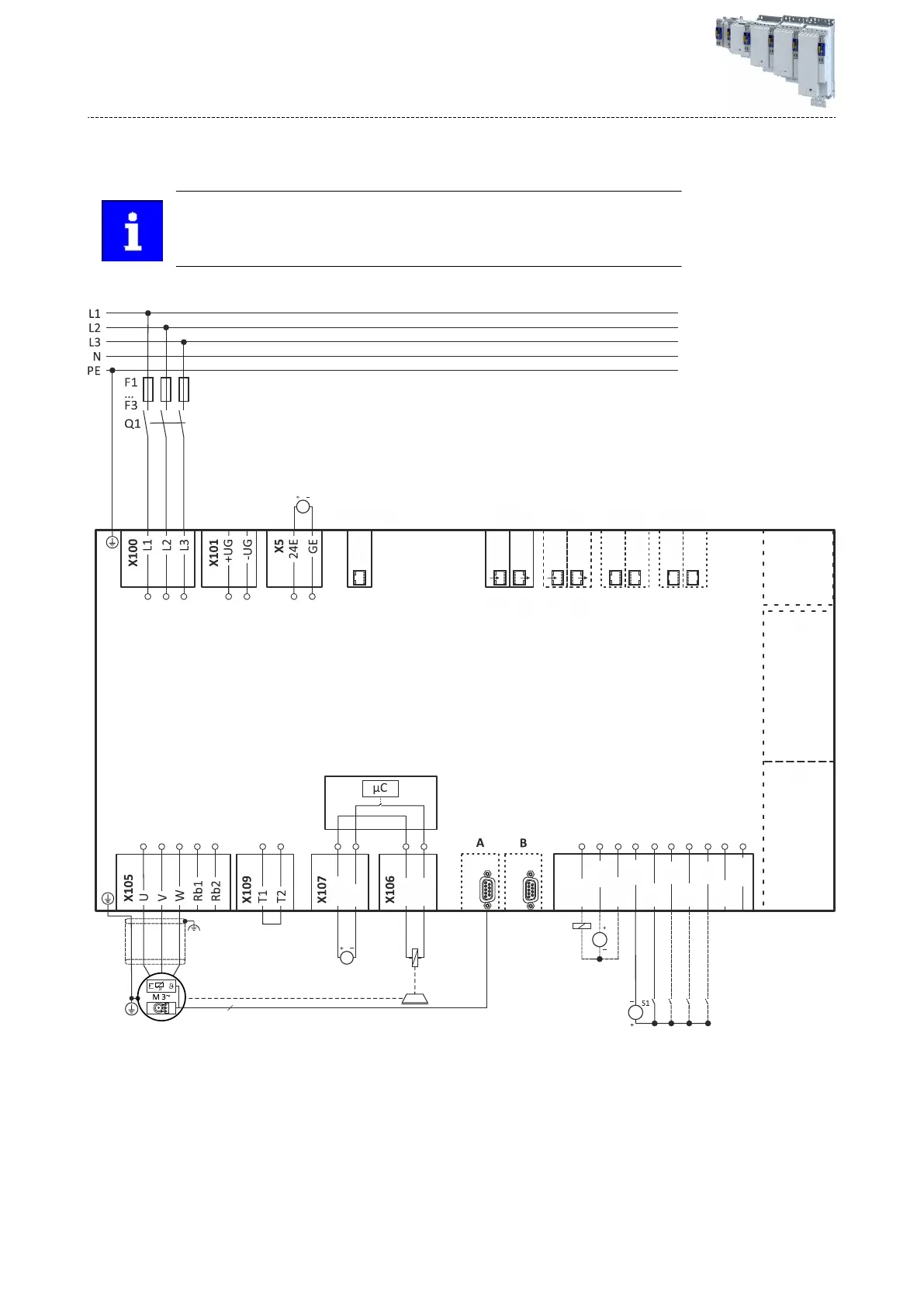
Connecon diagrams
A mains choke is required for the oper
aon of inverters ≥ 15 kW.
The connecon plan is valid for the inverters I95AExxxF.
X257
X256
PROFINET
X247
OUT
X246
IN
EtherCAT
X237
OUT
X236
IN
onboard
EtherCAT
X16
Engineering port
X267
X266
EtherNet/IP
X83
X82
X1
n
EYF
GB
24B
DC 24 V SELV/PELV
(+19.2 V ... +28.8 V)
BD2
BD1
DC 24 V SELV/PELV
(+19.2 V ... +28.8 V)
DC 24 V SELV/PELV
(+19.2 V ... +28.8 V)
X3
GDO
DO1
24O
GDI
DI1
DI2
DI3
DI4
AI1-
AI1+
DC 24 V SELV/PELV
(+19.2 V ... +28.8 V)
3/N/PE AC 480 V
3/PE
AC 340 V ... 528 V
45 Hz ... 65 Hz
Fig. 11: Wiring example
S1 Start/stop
Fx
Fuses
Q1 Mains contactor
EYF Lenze system cable
--- Shown with dashes = opons
A connecon diagram for the terminal X1 can be found under: 4Basic Safety - STO ^ 161
A c
onnecon plan for the terminals X82 and X83 can be found under: 4Extended Safety ^ 163
Electrical ins
tallaon
Mains connecon
3-phase mains connecon 480 V
144
 Loading...


