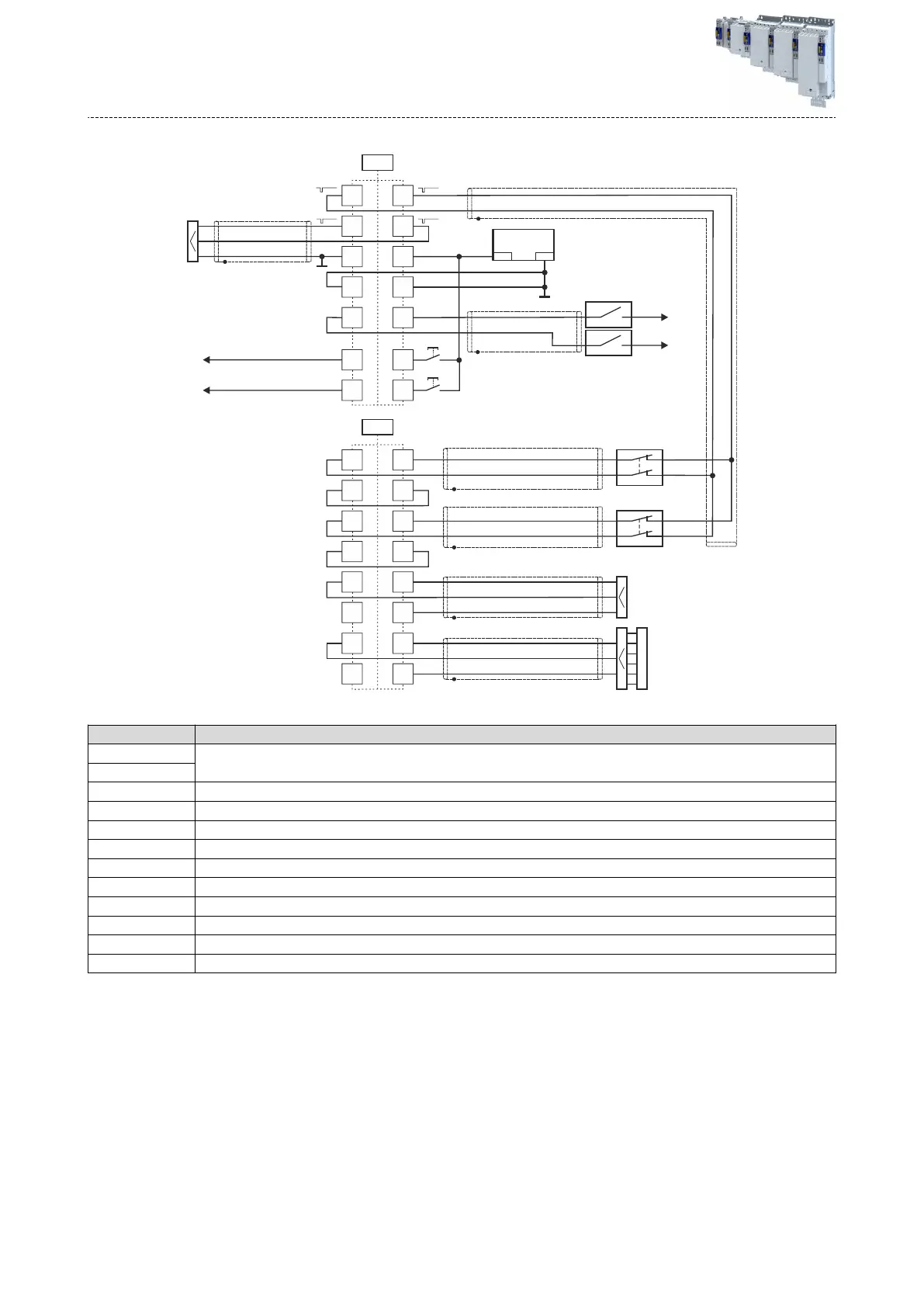
Connecon diagr
am
②
①
③
④
⑤
⑥
"
"
"
"
"
"
"
DC 24 V
SELV PELV/
+24 V
0 V
S4
S3
S1
SHOM
SHOM
S2
GS
O1A
CLA
K
GS
IRS
AIS
AIE
L
IRL
AIS
O1B
AIE
GSI
24S
X82
I3B
GI3
I4B
GI4
GI1
I2B
GI2
I1B
GS
I2A
GS
I3A
GS
GS
X83
CLB
I4A
I1A
Fig. 14: Sample circuit
Name Meaning
S1
Passive sensor with channel A and B
Pr
otected installaon for category 4 according to EN ISO 13849-2 required.
S2
S3 Acve sensor: Higher-level safety controller
S4 Acve sensor: Lightgrid
① Safe output to upstream safety control
② External 24-V-supply of the safe output and the clock outputs (SELV/PELV)
③ Reference switch; see funcon "SHOM"
④ Reference switch; see funcon "SHOM"
⑤ Buon f
or restart acknowledgement
⑥ Buon for fault acknowledgement
K To "AIS" connecon of next device
L To "AIE" connecon of next device
Electrical ins
tallaon
Funconal safety
Extended Safety
164
 Loading...


