Device description
Leuze electronic GmbH + Co. KG BPS 307i 10
3 Device description
3.1 Device overview
3.1.1
General information
The BPS barcode positioning system uses visible red laser light to determine its position and its speed
value relative to a barcode tape that is affixed along the travel path. This takes place in the following steps:
• Read a code on the barcode tape (see following figure)
• Determine the position of the read code in the scanning beam
• Calculate the position to within less than a millimeter using the code information and the code position
relative to the device's center.
The position and speed values are then output to the controller via the host interface.
The BPS consists of device housing and interface connection hood for the connection to the control. The
BPS can optionally be delivered with display and optics heating.
The following connection hoods are available for the connection of the SSI interface:
• MS307 connection hood with M12 connectors
• MK307 connection hood with spring-cage terminals
• KB307 connection hood with cable
000040 000044 000048 000052 000056
000060 000064 000068
1
2
4
3
G40LeuzeG40Leuze Leuze G40LeuzeG40
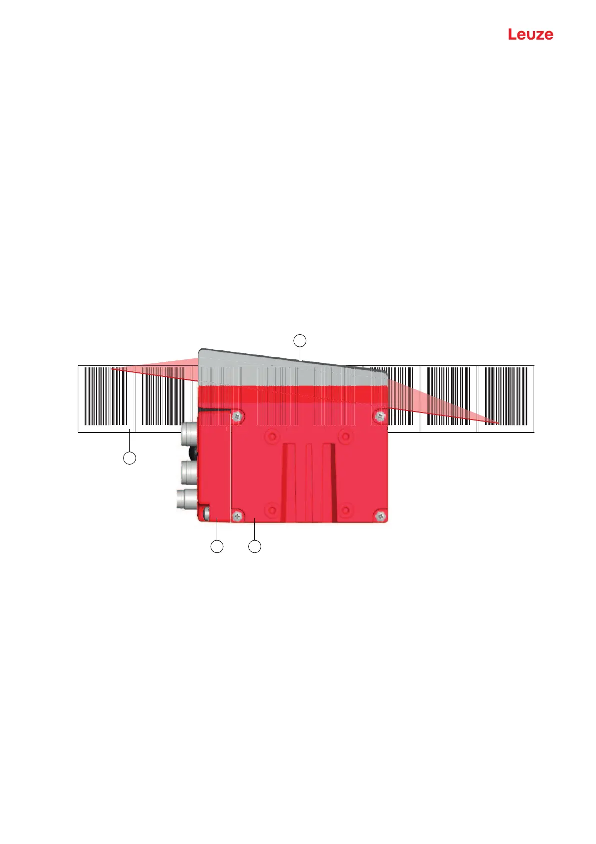
1 Bar code tape
2 Connection hood
3 Device housing
4 Middle of the scanning beam (device middle, output position value)
Fig.3.1: Device construction, device arrangement and beam exit
3.1.2
Performance characteristics
The most important performance characteristics of the barcode positioning system:
• Positioning with submillimeter accuracy from 0 to 10,000m
• For the control at high traverse rates of up to 10m/s
• Simultaneous position and speed measurement
• Working range: 50 to 170mm; enables flexible mounting positions
• Interfaces: PROFINET fieldbus, PROFIBUS fieldbus, SSI, RS232/RS422, RS485
• Binary inputs and outputs for control and process monitoring
• Configuration via webConfig tool or fieldbus
• Diagnosis via webConfig tool or optional display