Device description
Leuze electronic GmbH + Co. KG BPS 307i 23
3.4.3
Marker labels
Designation: BCBG30…ML… or BCBG40…ML…
Marker labels, which are affixed at the appropriate locations on top of the barcode tape, can be used to
trigger various functions in the superior control. The BPS detects the defined marker labels in the scanning
beam, decodes them, and makes them available to the control.
NOTICE
Distance between two marker labels!
Ä Make certain that there is only one marker label (or control barcode) in the scanning beam
at a time.
The minimum distance between two marker labels is determined by the distance between
the BPS and barcode tape and the resulting length of the scanning beam.
Definition of the marker label
The following combinations of letters and numbers may be used as marker labels:
• AA1
• BB1
• CC1
• DD1
• EE1
• FF1
• GG1
Marker labels are implemented as follows:
• Color red
• Height 47mm
• in grid dimension 40mm (BCBG40…ML)
• in grid dimension 30mm (BCBG30…ML)
• Code 128B
Marker labels are individual labels and are supplied in a packaging unit containing 10pieces.
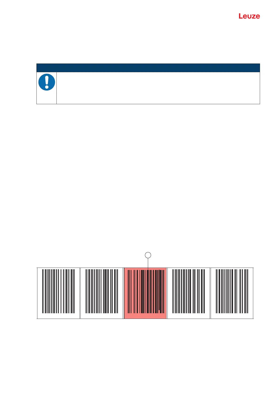
Arrangement when using the marker label with positioning
The marker label must be attached to the barcode tape aligned with the grid of the actual coding. A posi-
tion code should be visible before and after the marker label.
000040 000044 000048 0000052 000056
1
G40Leuze G40Leuze G40Leuze G40Leuze G40Leuze
A
A1
1 Marker labels
Fig.3.14: System arrangement of marker labels
Arrangement when using the marker label without positioning
The marker label must be positioned within the BPS's detection range.