Starting up the device – Basic configuration
Leuze electronic GmbH + Co. KG BPS 307i 52
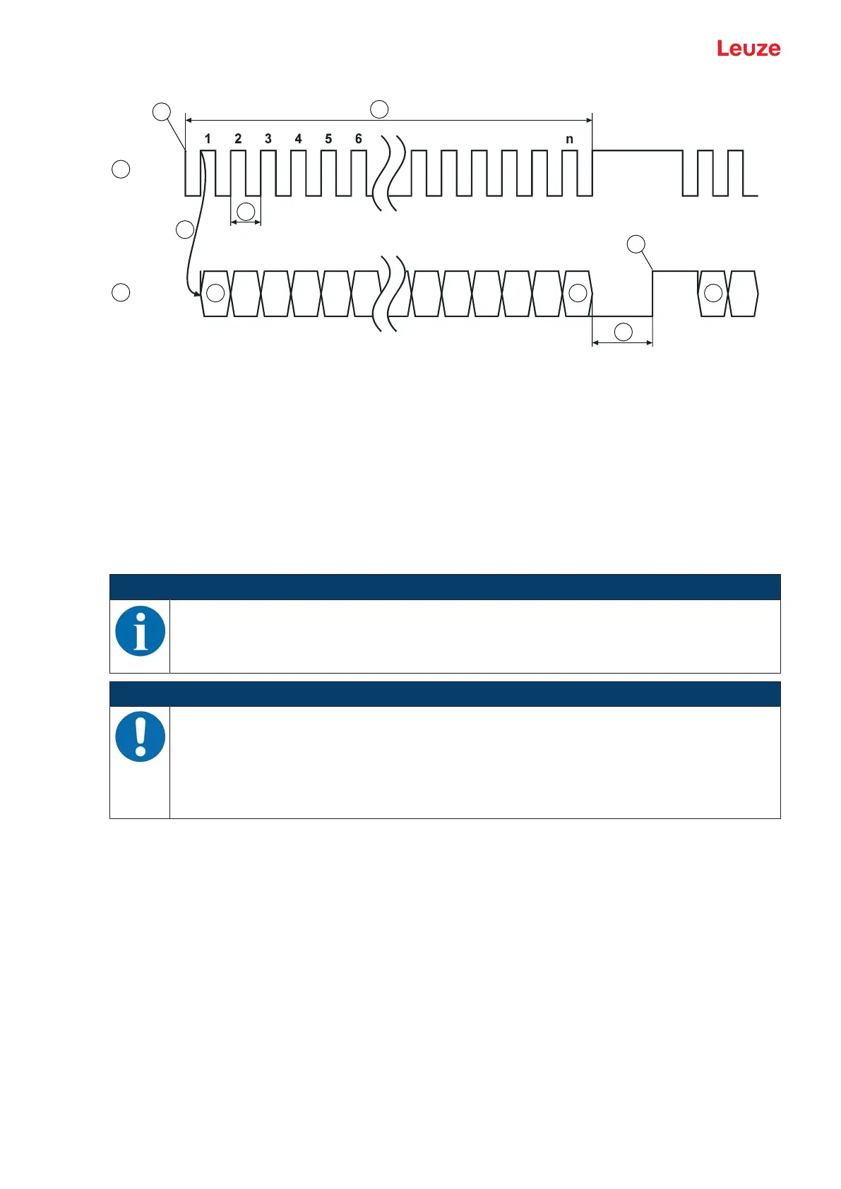
1 CLOCK
2 DATA
3 Clock sequence
4 First HIGH-LOW edge
5 Change LOW level to HIGH level
6 Bias level (HIGH)
7 T
SSI
(1/f
SSI
)
8 T
m
=20µs or 30µs
9 MSB
10 LSB (0)
Fig.8.1: SSI data transmission sequence diagram
NOTICE
If the off-cycle of data transmission is interrupted for longer than t
m
=20µs or t
m
=30µs , a com-
pletely new transmission cycle starts on the next cycle.
If a new transmission cycle is started before time t
m
elapses, the previous value is output again.
NOTICE
Factory setting: only positive position and speed values with SSI!
Ä In the factory setting, the SSI interface can only represent positive position and speed val-
ues.
If negative output values are ascertained due to the orientation of the BPS to the BCB or the
counting direction, the value 0 is output at the SSI interface!
In the event of a number overflow, all data bits are set to 1.
Factory settings of the SSI interface parameters
• Data encoding of the measurement values: Gray
• Sign: binary representation
• Transmission mode: 24measurement bits + 1error bit
• Resolution position value: 1mm
• Error bit: measurement error, LSB, 1=active
• Value of the error bit:
The error bit is not included in the Gray encoding of the measurement value.
The error bit is 1=active
• Update rate: 2ms
• SSI master clock frequency: 80kHz - 600kHz