Service Manual 217
Function
4.1 Initial setup
- There are 4 initial setup steps before running.
- All DIP switch setting must be completed before initial setup.
1) Step 1: Communication check
- If all model code is displayed in 7 segment including all sub unit, communicaiton between outdoor units is
normal.
- Sub unit lights on led 5 shortly whenever it transfer information to main unit.
- If led 5 does not light on periodically, check communication wires or dip switch setting.
2) Step 3 : PCB error check
-After 40 sec, error check begins.
■ Main unit
- All errors of uinits including sub units display in 7 segment.
- 2 leds representing inverter fan PCB and inverter compressor PCB communications twinkle if communica-
tions are normal.
■ Sub unit
- After 40 sec, led 1 is twinkle with period of 0.5sec.
- If electric phase is reverse or missed, led 6 is light on.
- Another leds exceot led 1 must turn off in initial setup steps.
3) Step 4: Auto addressing
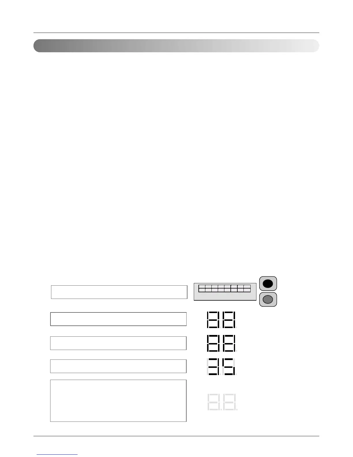
- Auto addressing begin when red button in Main PCB is pressed for 6 sec.
- During auto addressing, 7 segment on main PCB display "88"
- After auto addressing, no number is displayed anymore in 7 segment except the display of number of the
connected indoor unit found.
and every indoor unit's wired remocon display address of themselves.
Red button on for 6 sec.
Auto address starts
Auto address processing(max. 8 min.)
Total indoor units number found
(34 indoor units found)
Auto address process finishes.
Every indoor units display address
and total indoor units number is
disappreaed in 7 segment on main PCB
1 2 3 4 5 6 7 8
(6 sec.)