250 Trouble Shooting Guide
Checking Method for Key Components
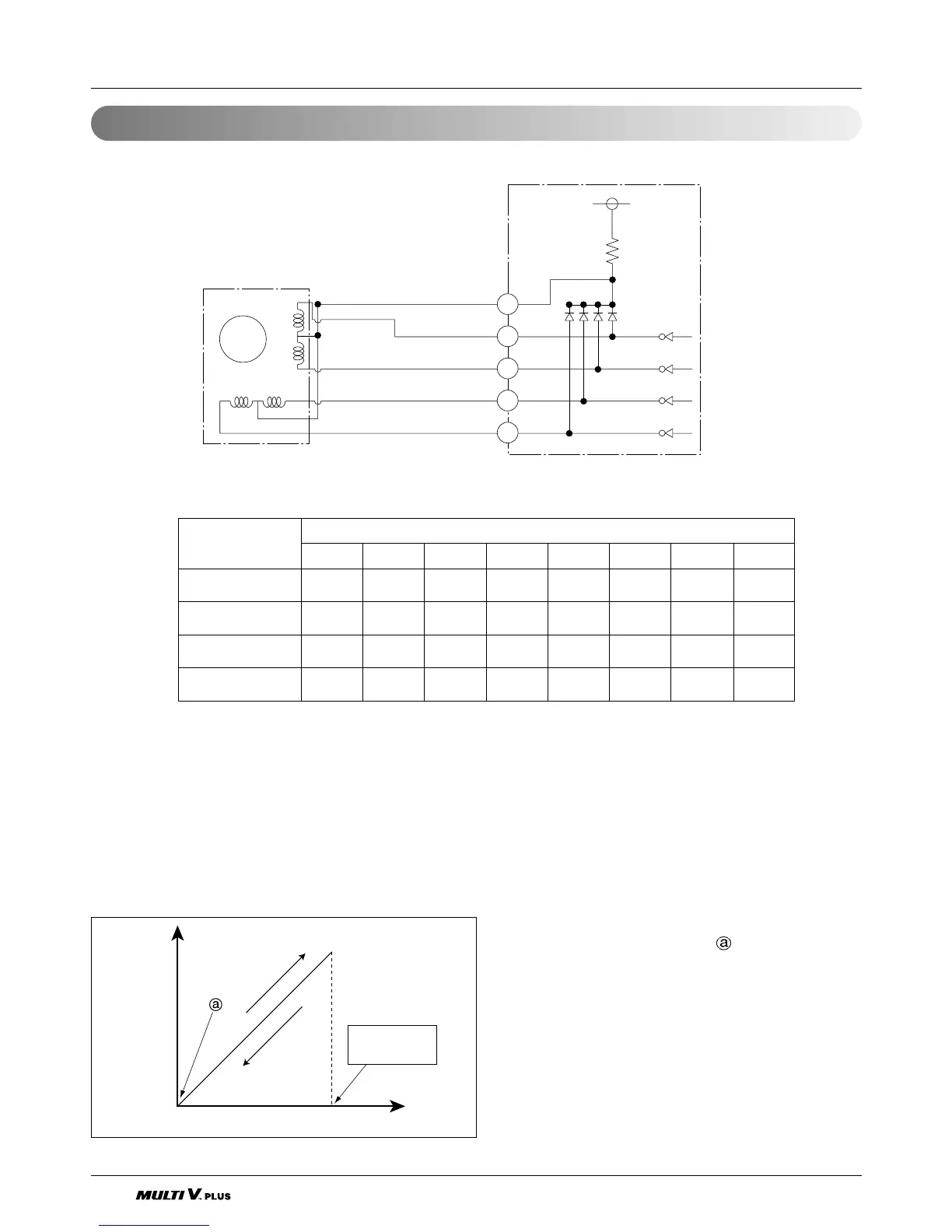
LEV
M
13
2
6
4
ø5 Red
White
Yellow
Orange
Blue
5
4
3
2
ø4
DC 12V Driving
circuit
ø3
ø2
ø1
1
ø4
ø3
ø2
ø1
• Pulse signal output value and valve operation
• Output pulse sequence
- In valve close state: 1 → 2 → 3 → 4 → 5 → 6 → 7 → 8 → 1
- In valve open state: 8 → 7 → 6 → 5 → 4 → 3 → 2 → 1 → 8
* 1. If LEV open angle is not change, all of output phase will be OFF
2. If output phase is different or continuously in the ON state, motor will not operate smoothly and start
vibrating.
• LEV valve operation
ø1 ON OFF OFF OFF OFF OFF ON ON
ø2 ON ON ON OFF OFF OFF OFF OFF
ø3 OFF OFF ON ON ON OFF OFF OFF
ø4 OFF OFF OFF OFF ON ON ON OFF
Output(ø) No.
Output state
12345678
Valve
open
Angle
close
pulse
open
Full open
1950 pulses
- At power ON, open angle signal of 2000 pulses out-
put and valve position is set to
If valve is operated smoothly, no noise and vibration
is occurred and if valve is closed. noise occurs.
- If you contact screw driver to LEV, and contact your
ear to driver hand grip. you can confirm the noise
from LEV.
- If liquid refrigerant is in LEV, the noise is lower.
2.3 Linear Empansion Valve