Page 47 of 76
Actuator with Parallel:
I/O specifications:
Input/Output Specification Comments
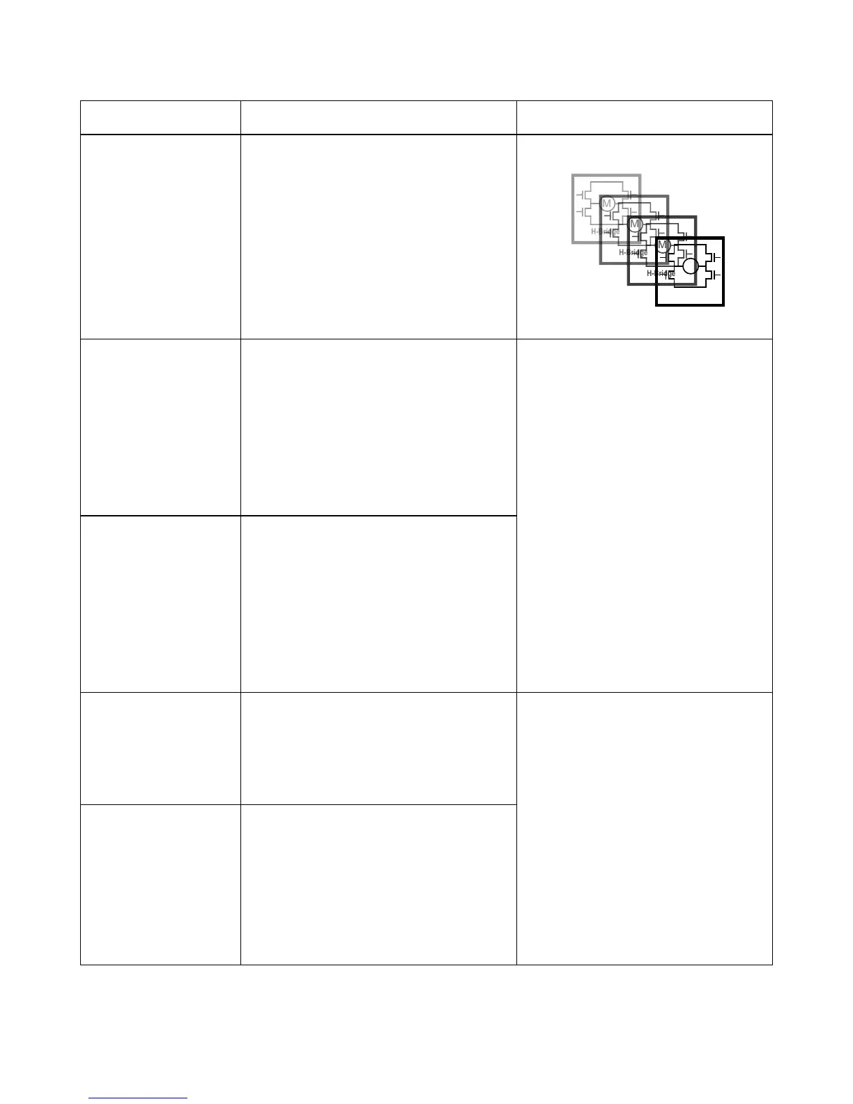
Description Parallel drive of up to 8 actuators. A
master actuator with an integrated
H-bridge controller controls up to 7
slaves.
The version with “IC option”
cannot be operated with PWM
(power supply).
See connection diagram,
fig. 17, page 46
Brown 12-24VDC + (VCC)
Connect Brown to positive
12V ± 20%
24V ± 10%
12V, current limit 25A
24V, current limit 13A
Note: Do not change the power
supply polarity on the brown and
blue wires!
The parallel actuators can run on
one OR separate power supplies
Power supply GND (-) is
electrically connected to the
housing
Current limit levels can be
adjusted through BusLink (only
one actuator at a time for
parallel)
If the temperature drops below
0°C, all current limits will
automatically increase to 30A
Blue 12-24VDC - (GND)
Connect Blue to negative
12V ± 20%
24V ± 10%
12V, current limit 25A
24V, current limit 13A
Red Extends the actuator On/off voltages:
> 67% of V
IN
= ON
< 33% of V
IN
= OFF
Input current: 10mA
It does not matter where the in/
out signals are applied. You can
either choose to connect the
signal cable to one actuator OR
you can choose to connect the
signal cable to each actuator
on the line. Either way this will
ensure parallel drive
Black Retracts the actuator