0 1 2 3 4 5 6 7 8 9
10
N° LNS : 4.869
R
HMI + cable
1
F1 F2 F3 F4
STOP
N° LNS : 4.875/**
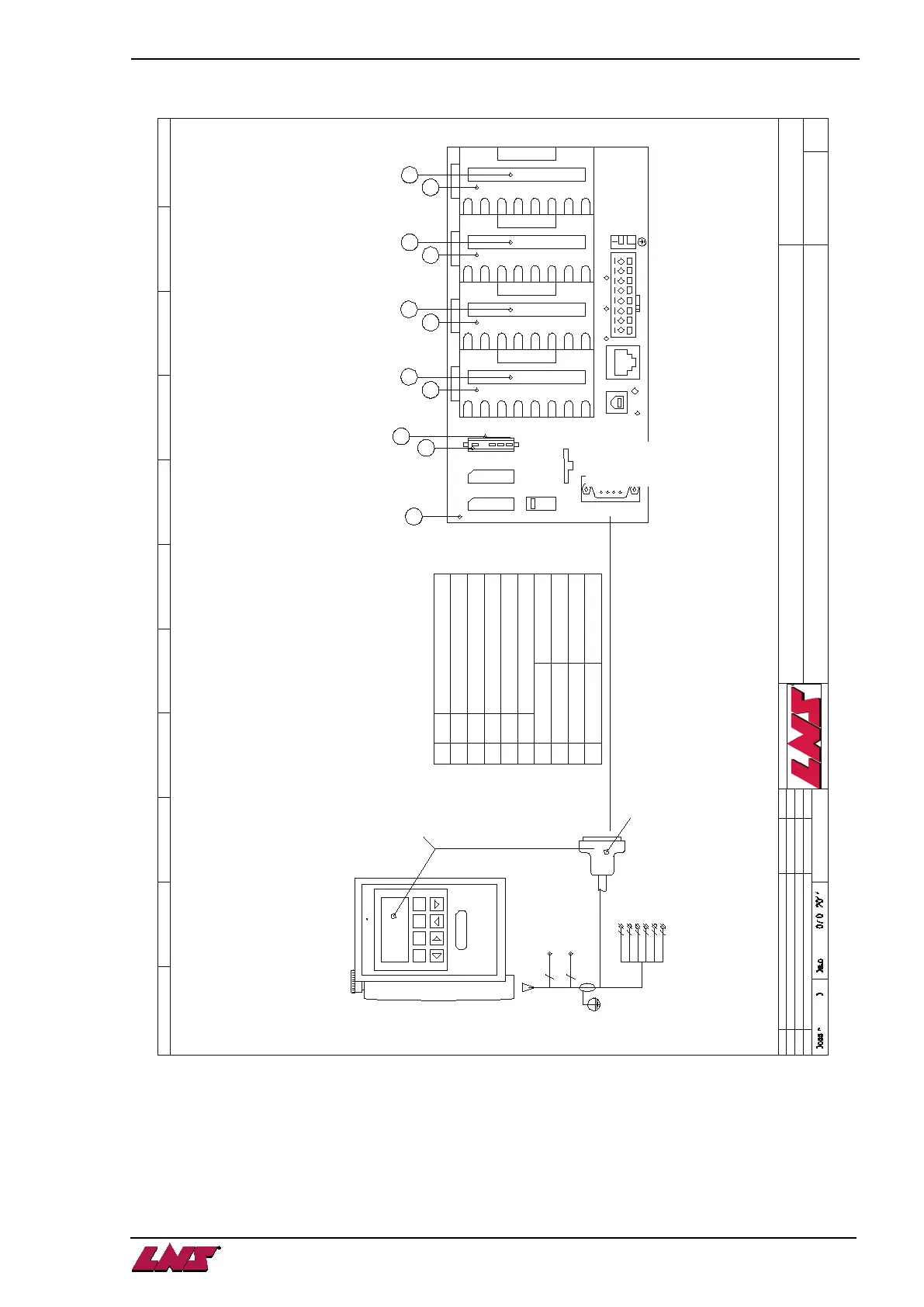
PCD3 5340 N°LNS 4.937
Rep Piece
1
2
3
4
5
7W1
PE
Brown
Brown
Blue
Yellow
Yellow
Blue
K8-S11
T1
EM1
EM4
EM2
EM3
EMERGENCY
STOP
Red
Black
+24V
0V/IN
6
7
8
9
N° LNS :
4.881/2.5 (2M/3M)
4.881/3.5 (12'/4M)
USB
Run/Halt Ethernet
D /D Int0 Int1WDWD+24GND
O C
Saia PCD3.M 5340
4.667
4.873
4.874
4.997
4.900
Description
Battery
Module 16 input 24VDC/0.2ms (E161)
Module 16 output 10...32VDC/0.5A (A460)
PLC PCD3.M5340 Z27
Module of battery
4.ES-112/E161-0
4.ES-112/E161-1
4.ES-112/A460-2
4.ES-112/A460-3
Cable 32x 900 mm
Cable 32x 900 mm
Cable 32x 790 mm
Cable 32x 790 mm
4
5
Saia-burgess
Batt
Run
Halt
Error
Run
0
Stop
Com/PGU
0
2
4
6
8
10
12
14
0
2
1
E
1
6
1
0
2
4
6
8
10
12
14
1
Link User
6
2
2
E
1
6
1
0
2
4
6
8
10
12
14
2
Power
7
3
3
A
4
6
0
0
2
4
6
8
10
12
14
3
8
3
9
A
4
6
0
H Added option production control page 2 + 6 15.01.2016
G Crossed wire Black and White on SR2
F
Rev.
Added arc suppressor Z1 on KM1A
Description
DE
19.08.2015 DE
23.06.2015 DE
Date To
ELECTRICAL DIAGRAMS
according to Directive 2006/42/CE
TRYTON
PCD3
112-40-620
Page 9 / 10
Index
H
M1
M2
Batt Module