HEADER
OPERAliON
Operating Variables
DELIVERY OPENING WIDTH
(continued)
To
adjust
delivery
opening
width:
1.
Release draper tension as follows:
Loosen bolt (A).
Loosen nut (B).
Slide bracket (C) towards idler roller.
NOTE: It may be necessary to tap bracket
(C) with a hammer to start it moving.
2.
Remove screws from draper
co~nector
slat.
RELEASE DRAPER TENSION
3.
Use this chart to position connector tubes at the appropriate rows
of
holes for desired opening size.
NOTE: The second row of holes at each set
is
provided to allow minor adjustments.
ii
ii
CENTER
DELIVERY
ilii{
OPEN'~G
WIDTH
DESIGNATED'
APPLICATION
·i
ii
>
(between
roU~rs)
Hi
:/r
,an~.COMMFf,~!S',,,::
i
Row
A
10
Row
F
(both
drapers)
32.5"
(825
mrn)
Opening
for
combine
models:
Case
2166,
1660,1460
New Holland TR97, TR87, TR96*,
TR86'
(0
1991
and after)
Row 8 to Row F (both drapers)
34.5" (875
mm)
Opening for combine models: Case 2188,1680,1480; MF8570;
NH TR96', TR86' ('1990 and prior), all Gleaner,
alllNhite
Row 8 to Row E (lJH draper)
42" (1067 mm)
Maximum opening for shifting decks on 21' Header.
Row C to Row E (RIH draper)
Row C to Row F (both drapers)
52.5" (1335 mm) Opening for combine models: all JD, all NH·TX, all Claas,
MF 860, 8460, 8450
Row C to Row E (both drapers) 54,5" (1384
mm)
Maximum opening for shifting decks on 30' Triple Delivery Hdr,
Row C to Row E
(LJH
draper)
61~
(1549 mm)
Maximum opening for
shifting decks on 25' Double & Triple
Row D to Row E (RIH draper)
DeHvery,
30' Double Delivery and 36' Headers.
Row D to Row F (both drapers) 66" (676 mm) Maximum opening on all header sizes
for
center delivery only,
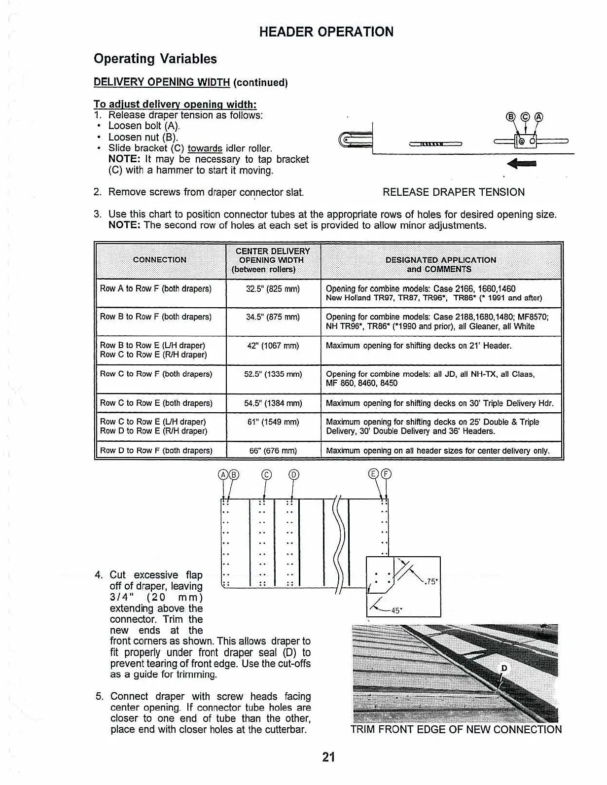
4.
Cut excessive flap
off of draper, leaving
3/4"
(20
mm)
extending above the
connector. Trim the
new ends at the
front corners
as
shown. This allows draper
to
fit
properly
under
front
draper
seal
(0)
to
prevent tearing
of
front
edge.
Use
the
cut-offs
as a guide for trimming.
5.
Connect draper with screw heads facing
center opening. If connector tube holes are
closer
to
one end of tube than
the
other,
place
end
with closer holes at the cutterbar.
21
TRIM FRONT EDGE OF
NEW
CONNECTION