TRANSPORT
Gauge Wheels
I Transport Option
CONVERTING
FROM
TRANSPORT
TO
FIELD
POSITION
A
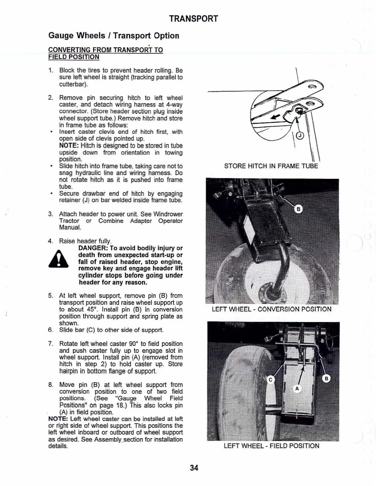
LEFT
WHEEL
- FIELD POSITION
.
~
STORE
HITCH IN FRAME
TUBE
5.
At
left wheel support, remove
pin
(8)
from
transport position and raise wheel support
up
to about
45°.
Install pin
(B)
in
conversion
position through support and spring plate
as
shown.
6.
Slide bar (C) to other side of support.
7.
Rotate left wheel caster goe to field position
and push caster fully up to engage slot
in
wheel support. Install pin (A) (removed from
hitch
in
step 2) to hold caster
up.
Store
hairpin
in
bottom
flange
of support.
8.
Move pin (B) at left wheel support from
conversion position to one of two field
positions. (See "Gauge Wheel Field
Positions" on page 18.) This also locks pin
(A)
in
field position.
NOTE: Left wheel caster can
be installed at left
or
right side
of
wheel support. This positions the
left wheel inboard
or
outboard
of
wheel support
as desired. See Assembly_section for installation
details.
4.
Raise header fully.
DANGER: To
avoid
bodily
injury
or
death
from
unexpected
start-up
or
fall
of
raised header,
stop
engine,
remove
key
and engage header
lift
cylinder
stops
before
going
under
header
for
any
reason.
1.
Block the tires to prevent header rolling.
Be
sure left wheel is straight (tracking parallel to
cUUerbar).
2.
Remove pin securing hitch
to
left wheel
caster, and detach wiring harness
at
4-way
connector.
(Store
header
section
plug
inside
wheel support tube.) Remove hitch and store
in frame tube as follows:
Insert caster clevis end
of
hitch first, with
open side
of
clevis pointed up.
NOTE:
Hitch
is
designed
to
be
stored
in
tube
upside down from orientation
in
towing
position.
Slide hitch into frame tube, taking care not to
snag hydraulic line and wiring harness. Do
not rotale hitch as
it
is pushed inlo frame
tube.
Secure drawbar end
of
hitch
by
engaging
retainer (J) on bar welded inside frame tube.
3.
Attach header
to
power unit. See Windrower
Tractor
or
Combine Adapter Operator
Manua1.
34