TRANSPORT
Gauge Wheels / Transport Option
CONVERTlNG
FROM
FIElD
POSITION
TO
TRANSPORT
At
LlH end (continued);
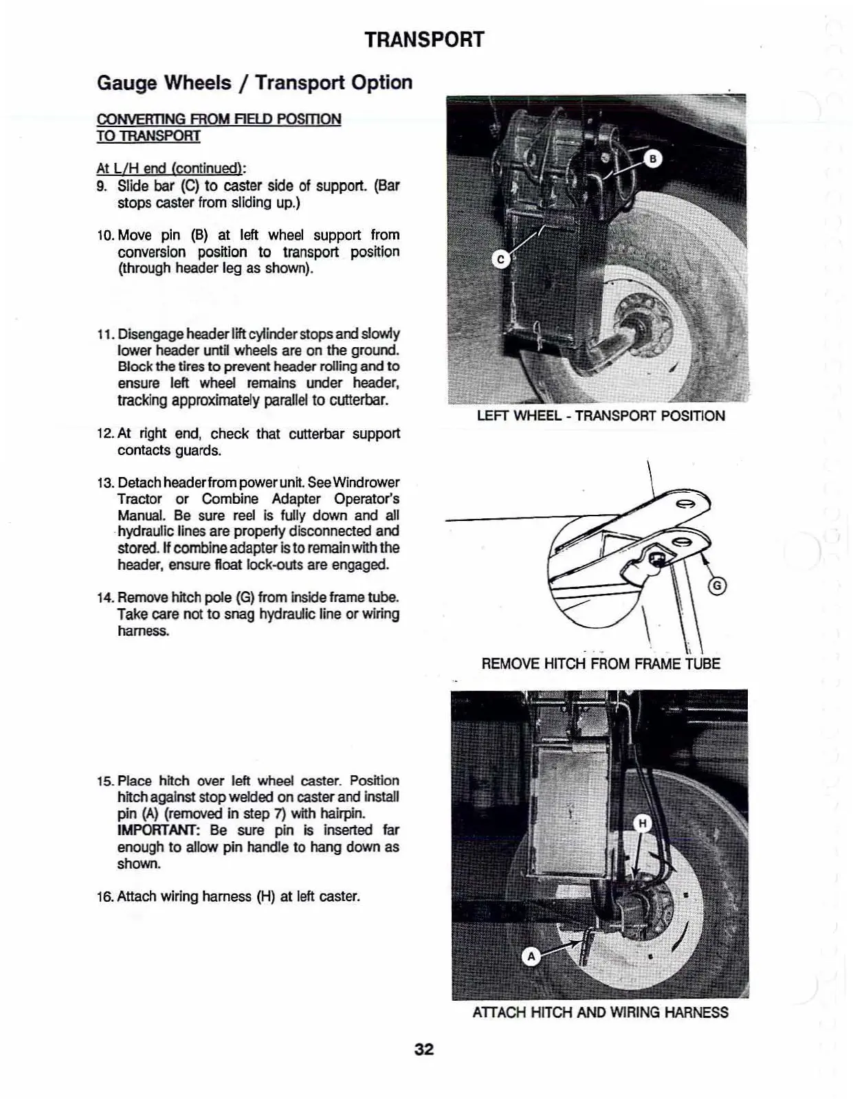
9.
Slide
bar
(C)
to caster
side
of
support.
(Bar
stops caster
from
sliding
up.)
10.
Move
pin
(B)
at
left
wheel
support from
conversion
position
to
transport
position
(through header leg as shown).
11.
Disengage headerlift cylinder stops
and
s1Q\A11y
lower header until wheels are on the ground.
Block the tires
to
prevent header rolling and
to
ensure
left
wheel remains under header.
tracking
approximately
parallel
to
cutterbar.
12.
At right
end,
check that cutterbar support
contacts guards.
13.
Detach
headerfrom power
unit.
See
Windrower
Tractor or Combine Adapter Operator's
Manual.
Be
sure
reel
is
funy
down
and
all
-hydraulic lines are properly disconnected and
stored.
"combine
adapter
Is
to
remain
with
the
header. ensure float Iock-outs are engaged.
14.
Remove
hitch pole
(G)
from inside
frame
tube.
Take care not
to
snag hydraulic line
or
wiring
harness.
LEFT
WHEEL
-
TRANSPORT
POSITION
. "
"'
\
REMOVE
HITCH
FROM
FRAME
TUBE
15. Place hitch over left
wheel
caster. Position
hitch against
stop
welded
on
caster and install
pin
(A)
(removed
in
step
7)
with
hairpin.
IMPORTANT: Be sure pin
Is
inserted far
enough
to
allow pin handle
to
hang
down
as
shown.
16.
Attach wiring harness (H)
at
left caster.
ATTACH
HITCH
AND
WIRING
HARNESS
32