Page 2
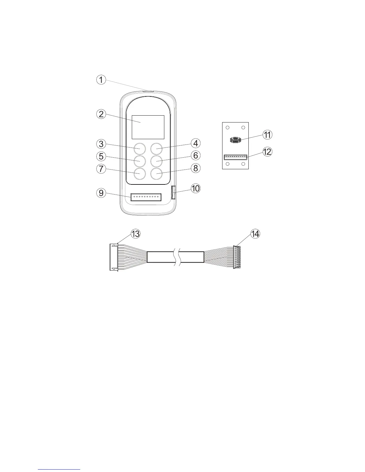
1. External Illustrations
1. Infrared sensors 8. “WRITE” button
2. LCD screen 9. Programming port
3. “
↑” button 10. Mini USB Port (for firmware update)
4. “
↓” button 11. I-Chip port
5. “BACK” button 12. I-Chip programming board connector
6. “
→” button 13. Connector to programming port
7. “READ” button 14. Connector to I-Chip programming board
(TX & RX) → Programming for both transmitter and receiver
(TX) → Programming for transmitter only
(RX) → Programming for receiver only