EC-30C | 1.00.02 +49 2102 935 888 www.mc-techgroup.com 41
8.2 Wall and rack mount
Note
The tubes for condensate removal will be directly connected to the
DN10/12 mm connectors at the bottom of the heat exchangers.
These condensate removal connectors stick out of the bottom plate
of the cooler housing.
2
3
1
Abmessungen in mm [Inch]
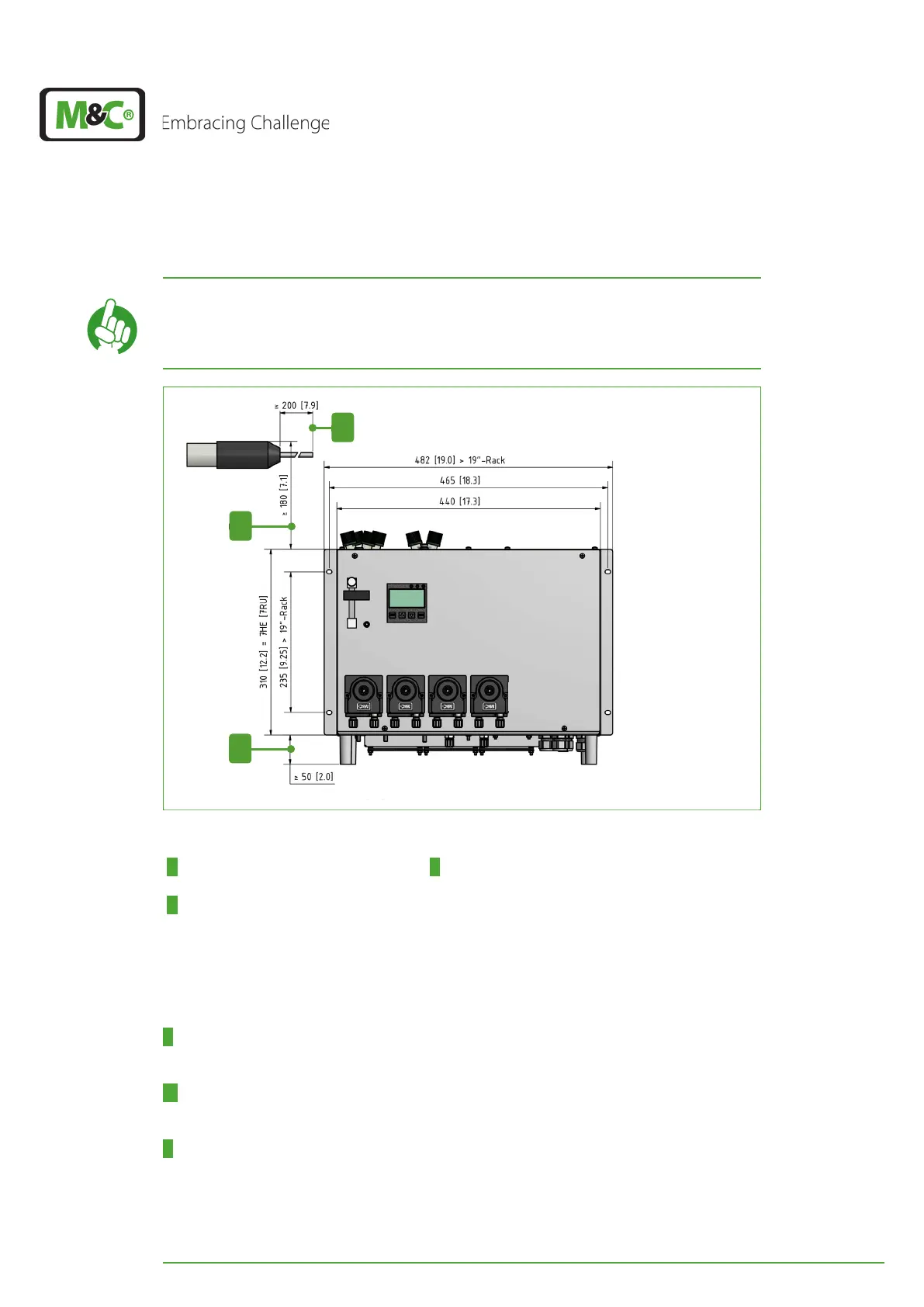
Fig. 30: Min. assembly dimensions (unit with optional peristaltic pumps)
1 Min. distance between isolation and
attachment point of the unit
2 Min. installation space above the EC-30C
3 Min. installation space below the
EC-30C
Please follow these instructions for mounting of the EC-30C (numbers correspond to Fig.
30 on page 41):
1 For heated gas sample lines, the insulated part of the line must end at least 200 mm
(7.87“) before the line reaches the device.
2 Please provide a minimum of 180 mm (7.09“) installation space above the unit for the
tubing. Make sure that outgoing air can exit from the upper side of the device.
3 Provide a min. of 50 mm (1.97“) installation space below the unit for tubing, air intake
and maintenance access. Our recommendation: min. 100 mm (3.94“).
Beispiel-Montage
Die M&C-Sonde SP180-H ist für den stationären Einsatz konzipiert. M&C erwartet bei fach-
gerechter Auswahl und Montage eine lange Funktionsfähigkeit und ein Minimum an War-
tung. Die optimale Betriebseinbaulage ist horizontal mit ca. 10° Neigung zum Prozess.
Abb.
Abb. n: Sondenmontage
A R2“-Gewinde-Montagefitting, Art.Nr. 20S9005
B Dichtung je nach Flanschgröße
1 Dichtung 3/4“, Art.Nr. 90S2080
2 Adapterflansch, Art.Nr. 20S9004
3 Dichtung DN65 PN6 Ø67, Art.Nr. 90S2077
4 Abgangs-Rohrverschraubung
5 Montageschelle für beheizte Leitung
6 3/4“-Innengewinde für Entnahmerohr
7 Metallschelle zur Montage der Isolierhaube
8 Isolierhaube mit Wartungsdeckel
Das gelieferte Entnahmerohr in das 3/4“-Innengewinde 6 im Flansch der Sonde mit der
3/4“-Flachdichtung 1 einschrauben und festziehen.