EC-30C | 1.00.02 +49 2102 935 888 www.mc-techgroup.com 47
8.5.1 Heat exchanger connections for tubing with purging
The EC-30C provides six connectors for three heat exchangers, which protrude through
the top panel of the device. The sample gas enters the cooler at the sample gas inlet of the
PCU heat exchanger.
The sample gas outlet DN 4/6 protrudes through the bottom plate of the cooler close to
the front plate on the left-hand side.
2
1
3
4
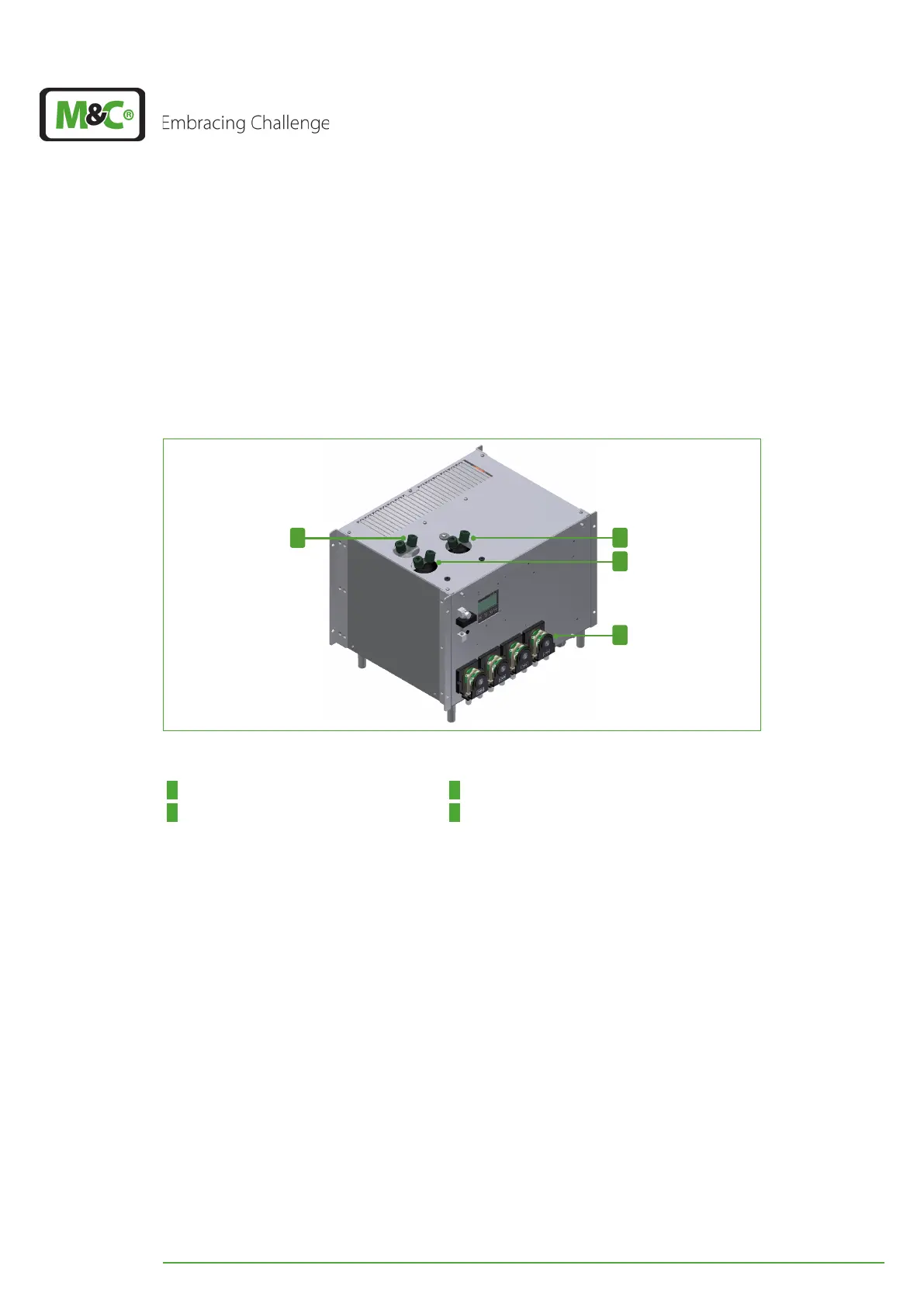
Fig. 36: Heat exchanger connections, tubing with purging
1 Heat exchanger pre-cooling unit 2 Heat exchanger DCU 2 (on the left)
3 Heat exchanger DCU 1 (on the right) 4 Heat exchanger purging: 4. peristaltic pump
(here: on the right)
The PCU heat exchanger has two connectors which are marked with arrows as gas inlet
and gas outlet. The connectors of the DCU heat exchangers are also marked with arrows.
Connect the gas inlet connectors of the DCU heat exchangers with a tee connector to the
outlet of the PCU heat exchanger.
The outlet connector of solenoid valve 2 sticks out of the bottom plate of the cooler locat-
ed in the middle, close to the front plate. Connect the gas outlet of solenoid valve 2 to the
fourth peristaltic pump.
Route the gas outlet of DCU 1 (on the right) through the top panel of the EC-30C to the
inside of the housing. Inside of the device connect the gas outlet of DCU 1 to the for-
ward-facing connectors of solenoid valve 1 and 2 with a tee.
Route the gas outlet of DCU 2 (on the left) through the top panel of the EC-30C to the in-
side of the housing. Inside of the device connect the gas outlet of DCU 2 to the back-
ward-facing connectors of solenoid valve 1 and 2 with a tee.