EC-30C | 1.00.02 +49 2102 935 888 www.mc-techgroup.com 65
10.6 Changing the compressor unit
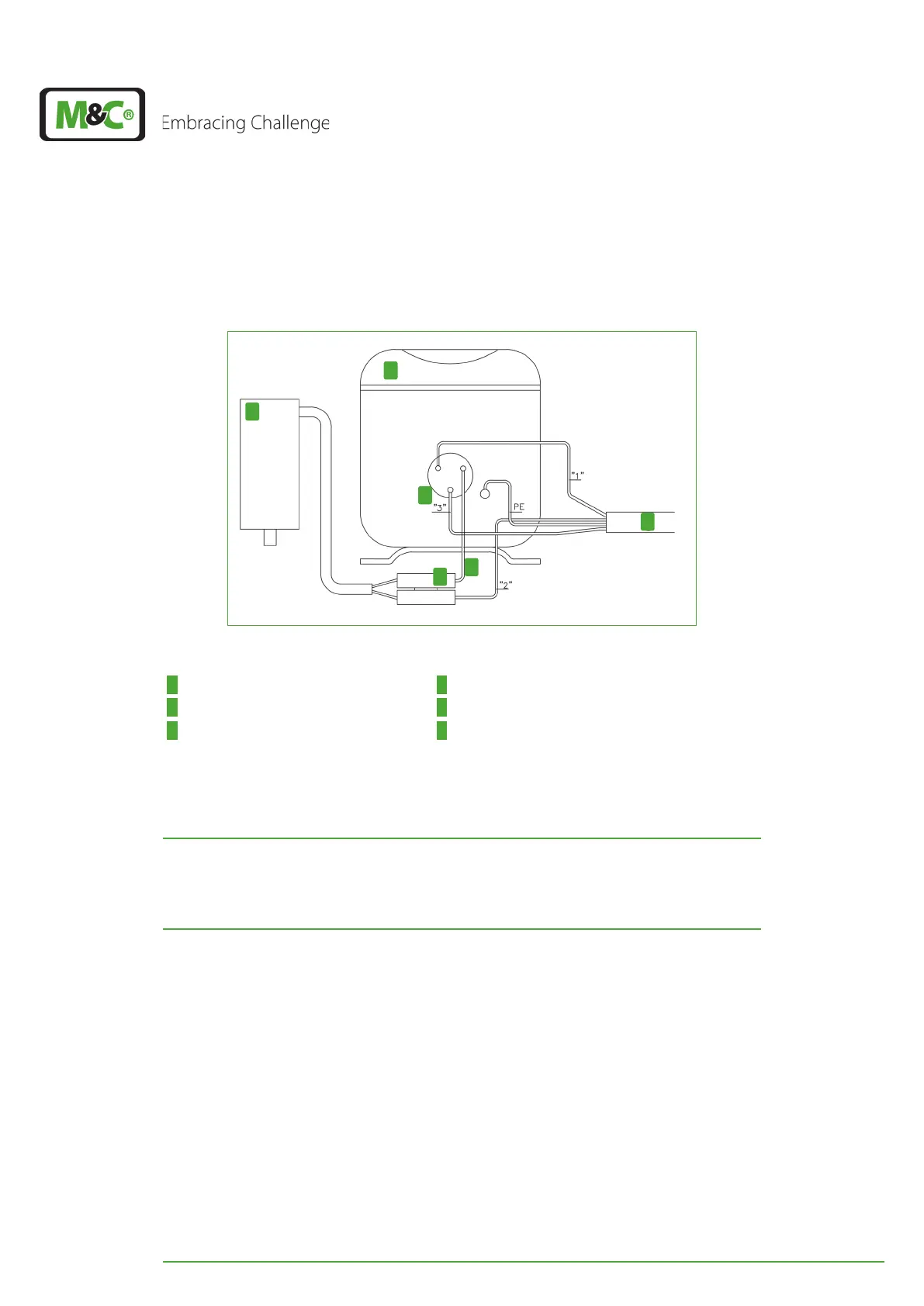
The compressor unit is connected to the electrical connections shown in Fig. 37 on page
50. The following figure shows the electrical connections of the compressor.
3
1
2
4
5
6
Fig. 41: Compressor: electrical connections
1 Compressor 2 Terminal area inside the compressor terminal box
3 Starting capacitor of the compressor 4 Controller cable from the main electronics
5 Connection wires 6 Flat connector
The four wires of the compressor unit are marked with the numbers ‘1’‚ ‘2’, ‘3’ and the letter
combination PE. These characters are printed on the power supply board belonging to
terminal X35. Connect the wires to the corresponding numbers and letters.
ATTENTION
Connect wires in the correct order!
Make sure to pay attention to the order of the printed numbers and
letters!