POWER TRAIN GRT9165 SERVICE MANUAL
7-32
Published 10-01-2020 Control # 699-00
Transmission Removal
1. Extend and set outriggers just enough to take up the
slack in the outrigger pads. Chock the wheels.
2. Remove the superstructure.
3. Remove the engine/torque converter from the crane as
an assembly. Refer to Engine Removal, page 7-2.
NOTE: The transmission weighs approximately 624.64 kg
(1377.1 lb) dry.
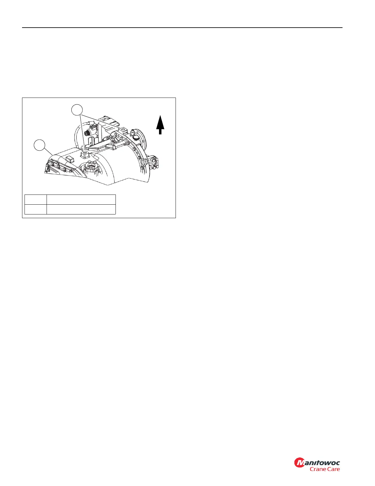
4. Attach an suitable lifting device to the lifting eyes (1,
Figure 7-24) on the top of the transmission (2) and take
up any slack.
5. Tag and disconnect hydraulic hoses.
6. Tag and disconnect electrical connectors.
7. Remove capscrews (2, Figure 7-23), split flanges (3), o-
ring (4), and dipstick tube (5) from the transmission (1).
Inspect the o-ring (4) and replace as necessary.
8. If not already done, remove capscrews (6), locknuts (7),
and driveshaft (8).
9. Disconnect front and rear drive shafts from transmission
drive shaft couplers (9). For more information, see Drive
Train, page 7-26.
10. Remove the locknuts (10), washers (11), shock mounts
(12), and capscrews (13) from both sides of the
transmission (1).
11. Using a suitable lifting device, remove the transmission
from the carrier frame. Place the transmission on a
suitable platform.
12. If necessary, remove capscrews (14), washers (15), and
installation brackets (16) from both sides of the
transmission (1).
Transmission Installation
NOTE: The transmission weighs approximately 624.64 kg
(1377.1 lb) dry.
1. If a new transmission (1, Figure 7-23) is to be installed,
remove all fittings and brackets from the old one and
install them in the same locations on the new
transmission.
2. Install the engine/torque converter to the carrier frame
as an assembly. Refer to Engine Removal, page 7-2.
3. If necessary, apply Loctite® 243 or equivalent to
capscrew (14) threads. Install installation brackets (16)
with capscrews (14) and washers (15). Torque
capscrews (14). For more information, see Fasteners
and Torque Values, page 1-16.
4. Attach an suitable lifting device to the lifting eyes on the
top of the transmission (1) and take up any slack. Lower
the transmission in to the carrier frame.Secure the
transmission (1) to the carrier frame with shock mounts
(12), washers (11), capscrews (13), and locknuts (10).
Torque locknuts (10). For more information, see
Fasteners and Torque Values, page 1-16.Connect to the
front and rear drive shafts to the drive shaft couplers (9)
on the transmission (1). For more information, see Drive
Train, page 7-26.
5. If necessary, install driveshaft (8) on transmission with
capscrews (6) and locknuts (7). Torque the capscrews
(6). For more information, see Fasteners and Torque
Values, page 1-16.
6. Install dipstick tube (5) to transmission (1) with new o-
ring (4), split flanges (3), and capscrews (2).
7. Install electrical connectors as tagged.
8. Install hydraulic hoses as tagged.
9. Service the crane as outlined under Servicing the Crane
after Transmission Overhaul, page 7-34.
10. Cycle all functions and observe for proper operation.
FIGURE 7-24
1
1 Lifting Eyes M25x2.5
2 Transmission
2
Top
10215

 Loading...


