Model: LC5296-XP-AT / LC5296-XP/LC5296-XP-I
Doc. Ref. no. :- m61D/om/101
Issue no. 17
User’s Manual Page 47 of 56
Hysteresis (Dead band): Hysteresis (Dead band) application is shown in the figure.
Direction:
All the figures here are shown considering the setting is direct (Normal). If the
settings are reversing (Fail Safe), the relays will behave exactly the opposite.
However, it’s worth mentioning that the relays will be in off (de-energized state on
Power on / reset condition). They will energize only after approximate 5 seconds.
When alarm type none is selected, ALRAM relay status depends on Direction.
Delay:
A time delay can be provided for the actual output. The relay will operate after the
set delay time.
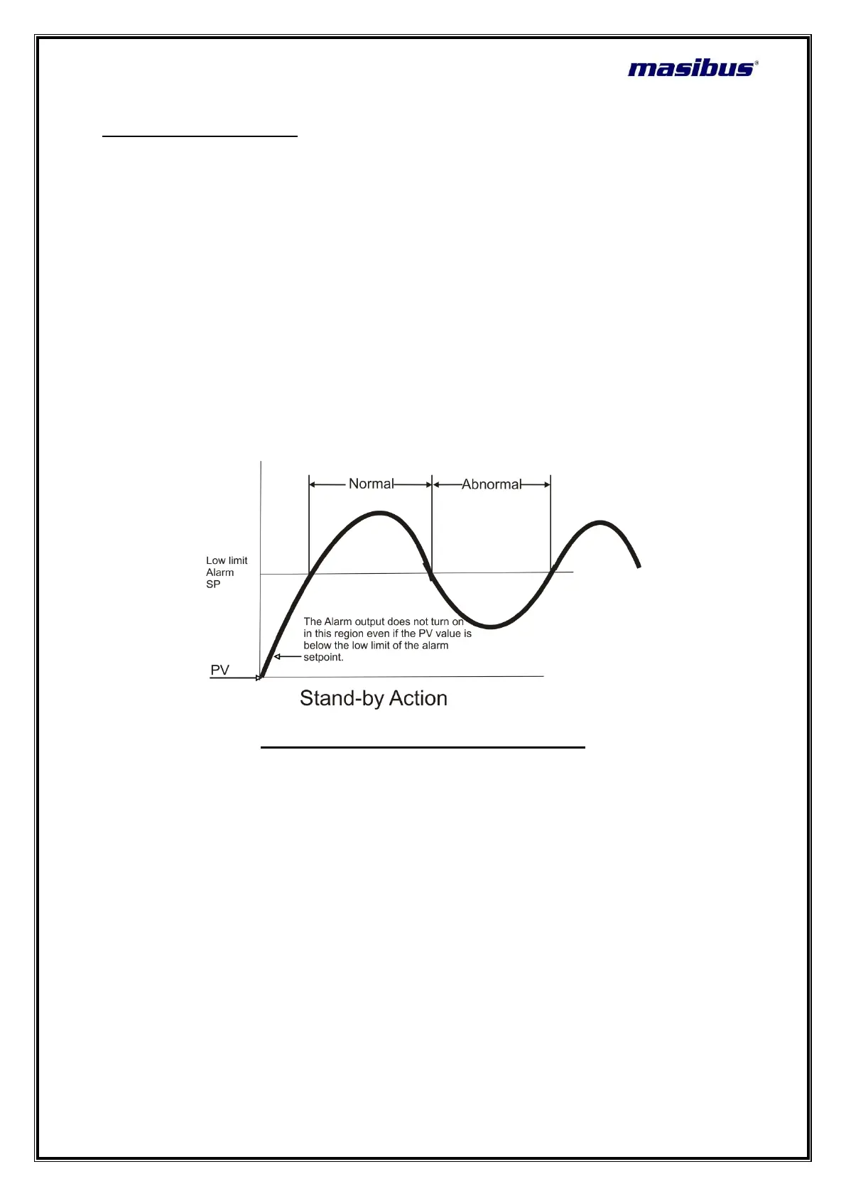
Standby operation:
For alarm types, 9 to 14, the relay action happens only after the PV has crossed the
SP after power on.
Example:-
FIGURE 9.1. ALARM OUTPUT DIAGRAM
 Loading...