Rad-8 Signal Extraction Pulse Oximeter Operator’s Manual 4-1
4
operation
Introduction
To operate the Rad-
8 system effectively, the device must be set up correctly and the
operator must
■ Know how the oximeter derives its readings (see Section 1, Pulse Oximetry)
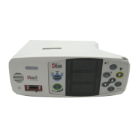
■ Be familiar with its control components and operation (see Section 2, System
Description).
■ Understand its status and alarm messages (see Section 5, Alarm Identification,
System Messages and Section 6, Troubleshooting).
Basic operation
GENERAL SETUP AND USE
1. Inspect the Rad-8 case for damage.
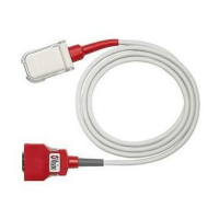
2. Connect a patient cable or a direct connect sensor to the Rad-
8 device. Make sure
it is a firm connection and the cable is not twisted, sliced or frayed.
3. If utilizing a patient cable, select a sensor that is compatible with the Rad-
8 and the
patient before connecting it to the patient cable. See section 8, Sensors and Patient
Cables. If using a single patient adhesive or disposable sensor, check that the emitter
(red light) and the detector are properly aligned. Remove any substances that may
interfere with the transmission of light between the sensor’s light source and detector.
4. Refer to the Directions for Use of the sensor before attaching the sensor to the patient.
5. Attach the Masimo sensor to the Patient. Connect the sensor to the patient cable with
the logos lining up; make sure it is a firm connection.
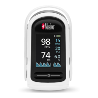
6. Press the Power button to turn the Rad-
8 on.
7. Verify all front-panel indicators momentarily illuminate and a tone is heard.
8. Verify the front-panel display is free of alarm and system failure messages (see
Section 5, Alarms and Messages).
9. Verify the LED shows the following:
■ Mode setting: Standard (Std) or Sleep (SLP) or Home (Hnn).
■ SpO
2
Low Alarm Limit and SpO
2
High Alarm Limit,
■ Pulse Rate Low Alarm Limit and Pulse Rate High Alarm Limit.
10. On the display, verify the readings for SpO
2
and pulse rate.
NOTE: “- - -” will flash on the numeric display until the SpO
2
and pulse rate readings
have stabilized (approximately 10 seconds).
11. On the LED
, verify the alarm limit settings. (See Setup Menu Level 1 in this section)
12. Verify that the patient alarms are functional by setting the high and low alarm limits
beyond the patient readings.
■ An alarm tone sounds.
■ The Alarm Bell flashes red
for high priority alarms.
■ The number value for the violated alarm limit will flash on the LED display.