19.8 Working with several cameras simultaneously 177
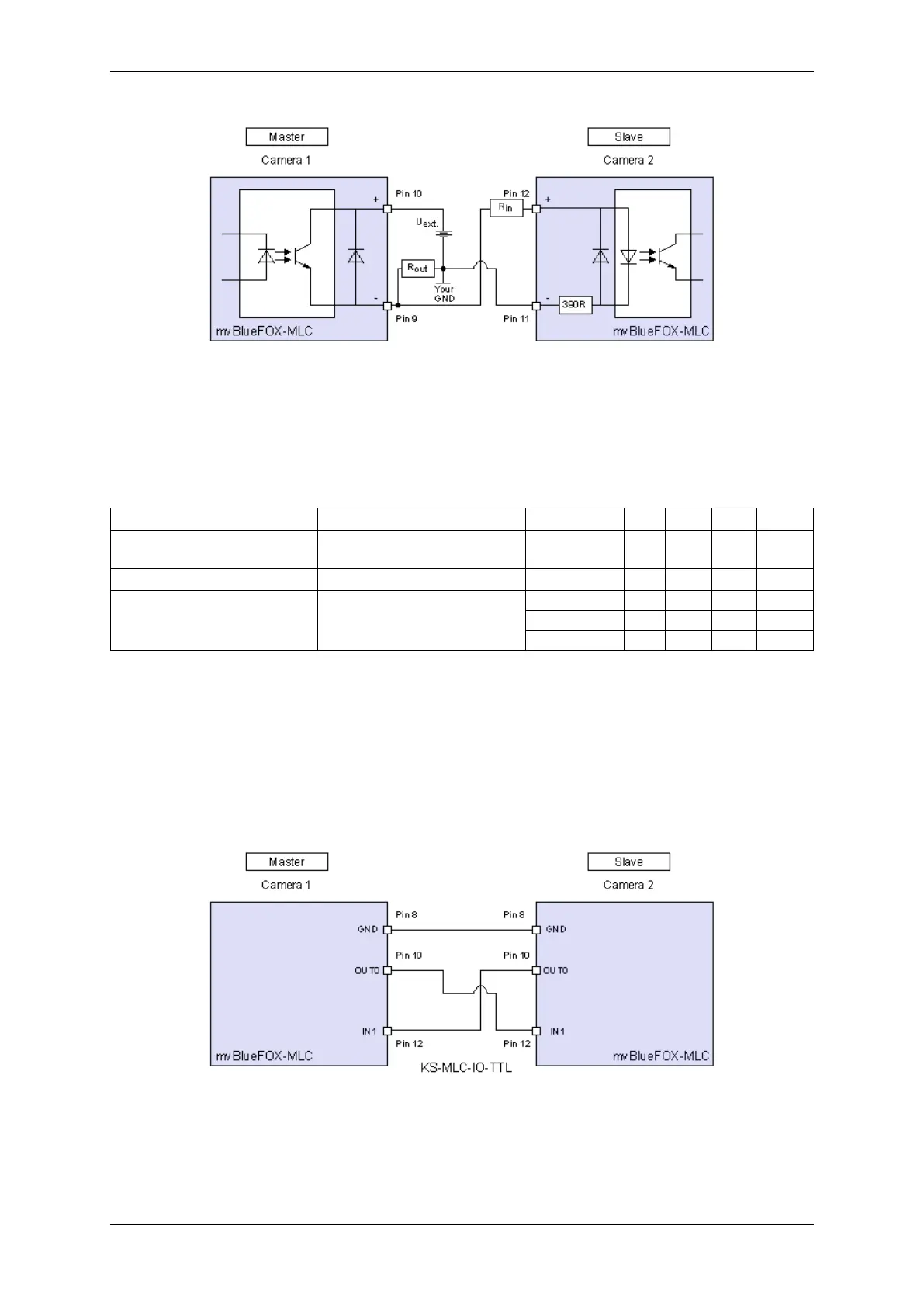
Figure 5: Connection with opto-isolated digital inputs and outputs
Symbol Comment Input voltage Min Typ Max Unit
U
ext.
External power 3.←-
3
30 V
R
out
Resistor digital output 2 kOhm
R
in
Resistor digital input
3.3 V .. 5 V 0 kOhm
12 V 0.68 kOhm
24 V 2 kOhm
You can add further slaves.
19.8.1.1.2 Connection using -UTW versions (TTL inputs and outputs)
The connection of the mvBlueFOX cameras should be like this:
Figure 6: Connection with TTL digital inputs and outputs
For this case we offer a synchronization cable called "KS-MLC-IO-TTL 00.5".
MATRIX VISION GmbH
 Loading...