8.2 Standard version (mvBlueFOX-xxx) 47
Pin Signal Description
1 IN0- Negative terminal of opto-isolated input
1
2 OUT0- Negative terminal of opto-isolated output (emitter of npn-phototransistor)
3 OUT1- Negative terminal of opto-isolated output (emitter of npn-phototransistor)
4 IN1- Negative terminal of opto-isolated input
∗
5 N/C
6 IN0+ Positive terminal of opto-isolated input
∗
7 OUT0+ Positive terminal of opto-isolated output (collector of npn-phototransistor)
8 OUT1+ Positive terminal of opto-isolated output (collector of npn-phototransistor)
9 IN1+ Positive terminal of opto-isolated input
∗
1
Voltage between + and - may be up to 26V, input current is 17mA.
8.2.1.1.1 Characteristics of the digital inputs
Open inputs will be read as a logic zero.
When the input voltage rises above the trigger level, the input will deliver a logic one.
Symbol Comment Min. Std. Max. Unit
U
IN_TTL
High level input voltage TTL logic 3 5 6.5 V
Low level input voltage TTL logic -
0.7
1 V
I
IN_TTL
Current TTL logic 8.←-
5
12 mA
U
IN_PLC
High level input voltage PLC logic 12 24 V
Low level input voltage PLC logic -
0.7
8 V
I
IN_PLC
Current PLC logic 17 25 mA
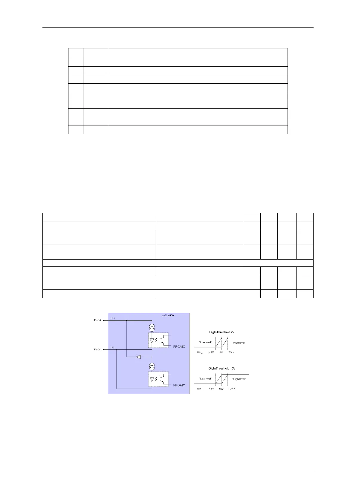
Figure 4: DigIn mvBlueFOX-xxx
In wxPropView (p. 77) you can change between
• TTL ("DigitalInputThreshold = 2V") and
• PLC ("DigitalInputThreshold = 10V")
MATRIX VISION GmbH