132 Appendix B: Technical information
When the board is configured in single-Medium or single-Full mode, the first
connector has the pinout described above, while the second connector has the
following pinout.
To interface with the above connectors, use a standard Camera Link cable. You
can purchase such a cable from your video source manufacturer, 3M Interconnect
Solutions for Factory Automation, Intercon 1, or other third parties. Note that
this cable is not available from Matrox.
❖ If using both Camera Link connectors to connect to the same video source
(single-Medium mode or single-Full mode), the cables you choose must be of the
same type and length. Otherwise, the cables can have different propagation delays.
8 X3+ Video input data X3 (positive). 21 X3- Video input data X3 (negative).
9 Xclk+ Clock input X (positive). 22 Xclk- Clock input X (negative).
10 X2+ Video input data X2 (positive). 23 X2- Video input data X2 (negative).
11 X1+ Video input data X1 (positive). 24 X1- Video input data X1 (negative).
12 X0+ Video input data X0 (positive). 25 X0- Video input data X0 (negative).
13 Inner shield Ground. 26 Inner shield Ground.
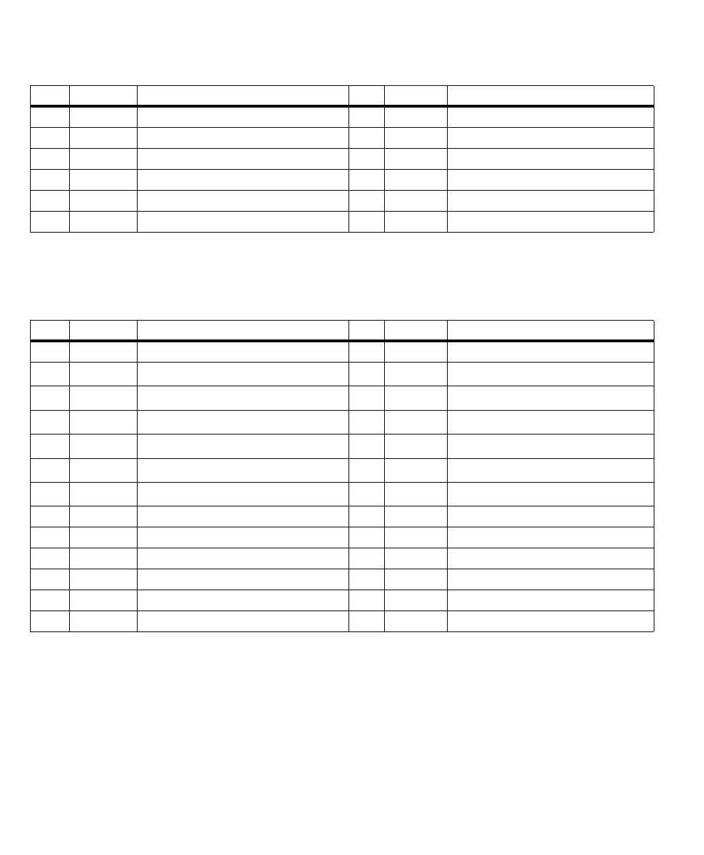
Pin Signal Description Pin Signal Description
Pin Signal Description Pin Signal Description
1 Inner shield Ground. 14 Inner shield Ground.
2Z3+
Video input data Z3 (positive).
1
15 Z3-
Video input data Z3 (negative).
1
3Zclk+
Clock input Z (positive).
1
16 Zclk-
Clock input Z (negative).
1
4Z2+
Video input data Z2(positive).
1
17 Z2-
Video input data Z2 (negative).
1
5Z1+
Video input data Z1 (positive).
1
18 Z1-
Video input data Z1 (negative).
1
6Z0+
Video input data Z0 (positive).
1
19 Z0-
Video input data Z0 (negative).
1
7terminated
Unused.
1
20 100 Ω
Unused.
1
8 Y3+ Video input data Y3 (positive). 21 Y3- Video input data Y3 (negative).
9 Yclk+ Clock input Y (positive). 22 Yclk- Clock input Y (negative).
10 Y2+ Video input data Y2 (positive). 23 Y2- Video input data Y2 (negative).
11 Y1+ Video input data Y1 (positive). 24 Y1- Video input data Y1 (negative).
12 Y0+ Video input data Y0 (positive). 25 Y0- Video input data Y0 (negative).
13 Inner shield Ground. 26 Inner shield Ground.
1. When the board is configured in single-Medium mode, these pins are reserved.