150 Appendix B: Technical information
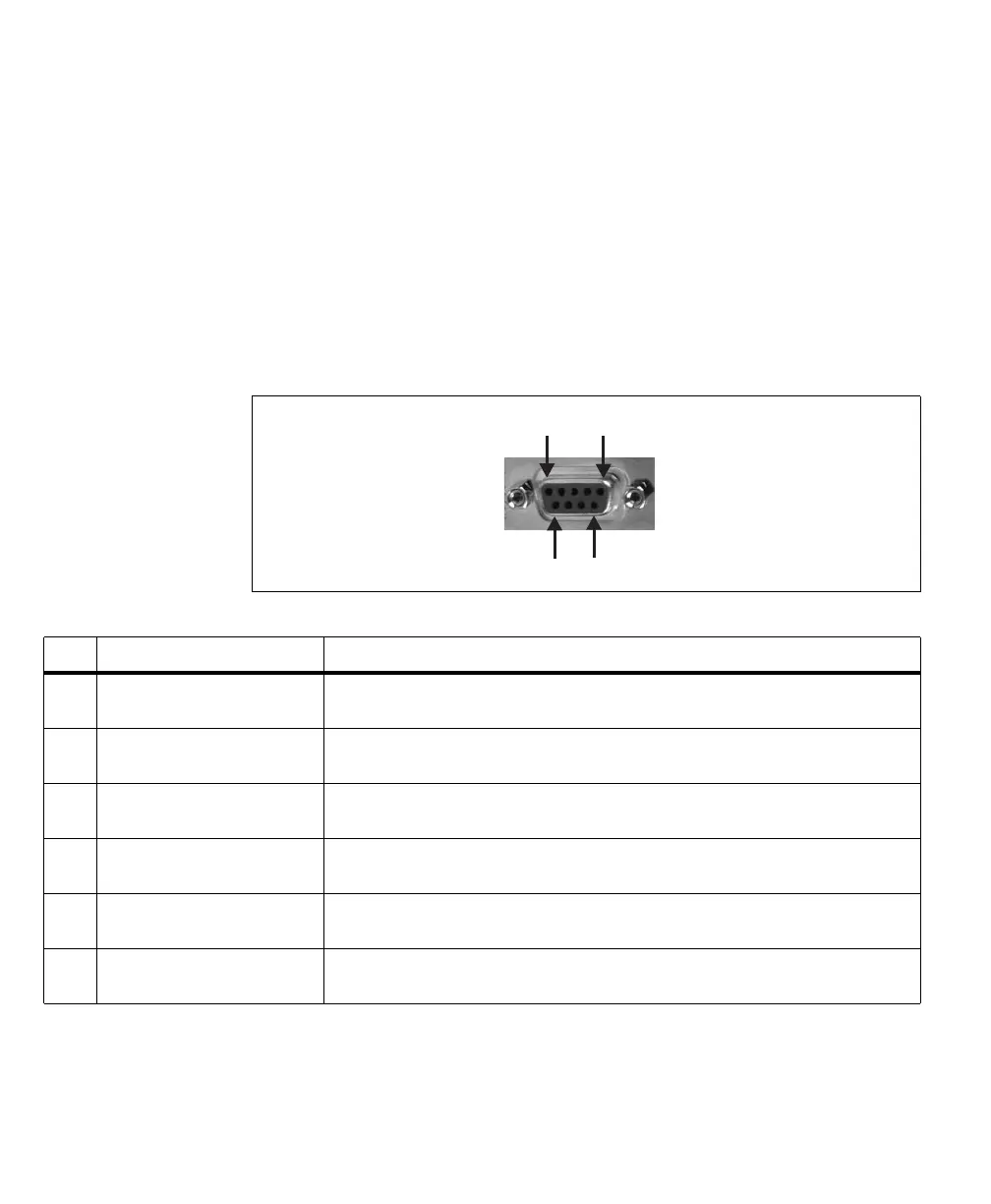
External auxiliary I/O connector 1
External auxiliary I/O connector 1 is a standard DB-9 female connector, located
on the bracket of the LVDS cable adapter board. It is used to receive opto-isolated
auxiliary input signals. It interfaces with the 50-pin internal auxiliary I/O
connector on the board, making the auxiliary signals accessible outside the
computer enclosure.
The pinout for this connector is as follows.The description of each (positive)
auxiliary signal states whether the signal is specific to an acquisition path and the
type of signals that can be routed onto it.
96
1
5
Pin Signal
1
Description
1 P2_OPTO_AUX(TRIG)_IN+ Opto-isolated auxiliary input for acq. path 2 (positive).
Supported signals: trigger input 1 or user-defined input 1.
2 P0_OPTO_AUX(TRIG)_IN- Opto-isolated auxiliary input for acq. path 0 (negative).
See pin 7 for more information.
3 P3_OPTO_AUX(TRIG)_IN- Opto-isolated auxiliary input for acq. path 3 (negative).
See pin 8 for more information.
4 P1_OPTO_AUX(TRIG)_IN+ Opto-isolated auxiliary input for acq. path 1 (positive).
Supported signals: trigger input 1 or user-defined input 1.
5 P1_OPTO_AUX(TRIG)_IN- Opto-isolated auxiliary input for acq. path 1 (negative).
See pin 4 for more information.
6 P2_OPTO_AUX(TRIG)_IN- Opto-isolated auxiliary input for acq. path 2 (negative).
See pin 1 for more information.