Connectors on Matrox Solios eCL/XCL dual-Base/single-Medium and eCL/XCL-F boards 133
External auxiliary I/O connector 0
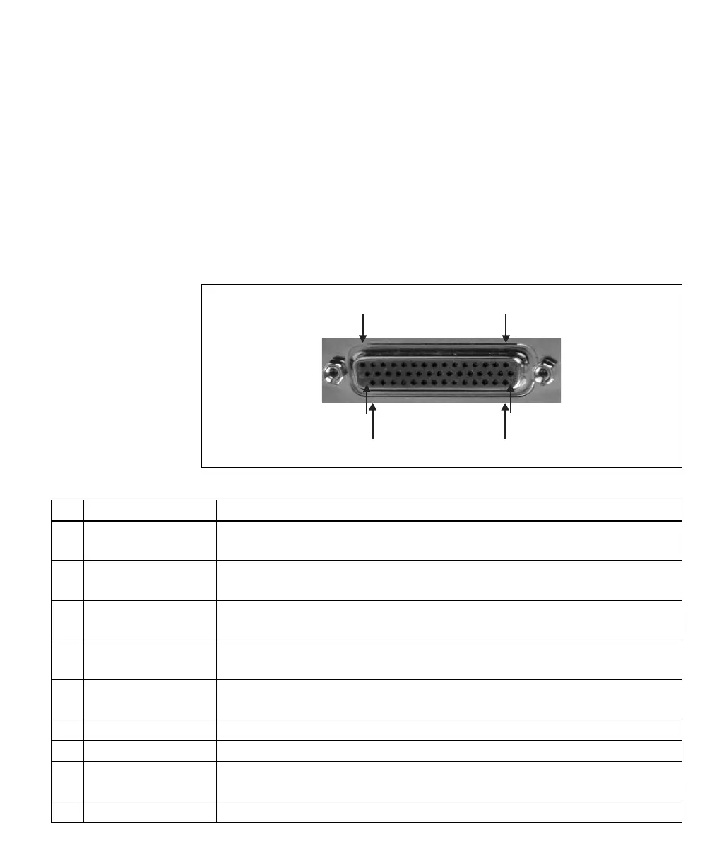
External auxiliary I/O connector 0 is a high-density DB-44 female connector,
located on the bracket of the cable adapter board. It is used to transmit timing
and synchronization signals, and transmit/receive auxiliary signals. It interfaces
with the 50-pin internal auxiliary I/O connector on the board, making the I/O
signals accessible outside the computer enclosure.
The pinout for this connector is as follows. The description of each (positive)
auxiliary signal states whether the signal is specific to an independent acquisition
path and the type of signals that can be routed onto it.
1
16
31
15
30
44
Pin Signal Description
1 P1_TTL_AUX_IO_1 TTL auxiliary input/output 1 for acq. path 1.
Supported signals: exposure output 0, exposure output 3, trigger input 1, user-defined input/output 3.
2 P1_LVDS_AUX_OUT1+ LVDS auxiliary output 1 for acq. path 1 (positive).
Supported signals: exposure output 1, user-defined output 6.
3 P0_LVDS_AUX_OUT1- LVDS auxiliary output 1 for acq. path 0 (negative).
See pin 19 for more information.
4 P0_LVDS_AUX_OUT0- LVDS auxiliary output 0 for acq. path 0 (negative).
See pin 20 for more information.
5 P1_LVDS_HSYNC_OUT- HSYNC output for acq. path 1 (negative).
See pin 6 for more information.
6 P1_LVDS_HSYNC_OUT+ HSYNC output for acq. path 1 (positive).
7 P1_LVDS_CLK_OUT+ Clock output for acq. path 1 (positive).
8 OPTO_AUX_IN0- Opto-isolated auxiliary input 0 for an unspecified acq. path (negative).
See pin 24 for more information.
9 NC Not connected.