156 Appendix B: Technical information
Ethernet connectors
The four Ethernet connectors are 8-pin connectors that terminate 4 twisted-pair
wires. They are used to receive video input signals between the video source and
the frame grabber, as per GigE Vision protocol, found in the IEEE 802.3-2002
standard.
To interface with the Ethernet connectors, use Category 5 unshielded twisted-pair
(Cat 5 UTP) cables. Alternatively, Category 5e or Category 6 unshielded twisted
pair cables can be used.
External auxiliary I/O connector
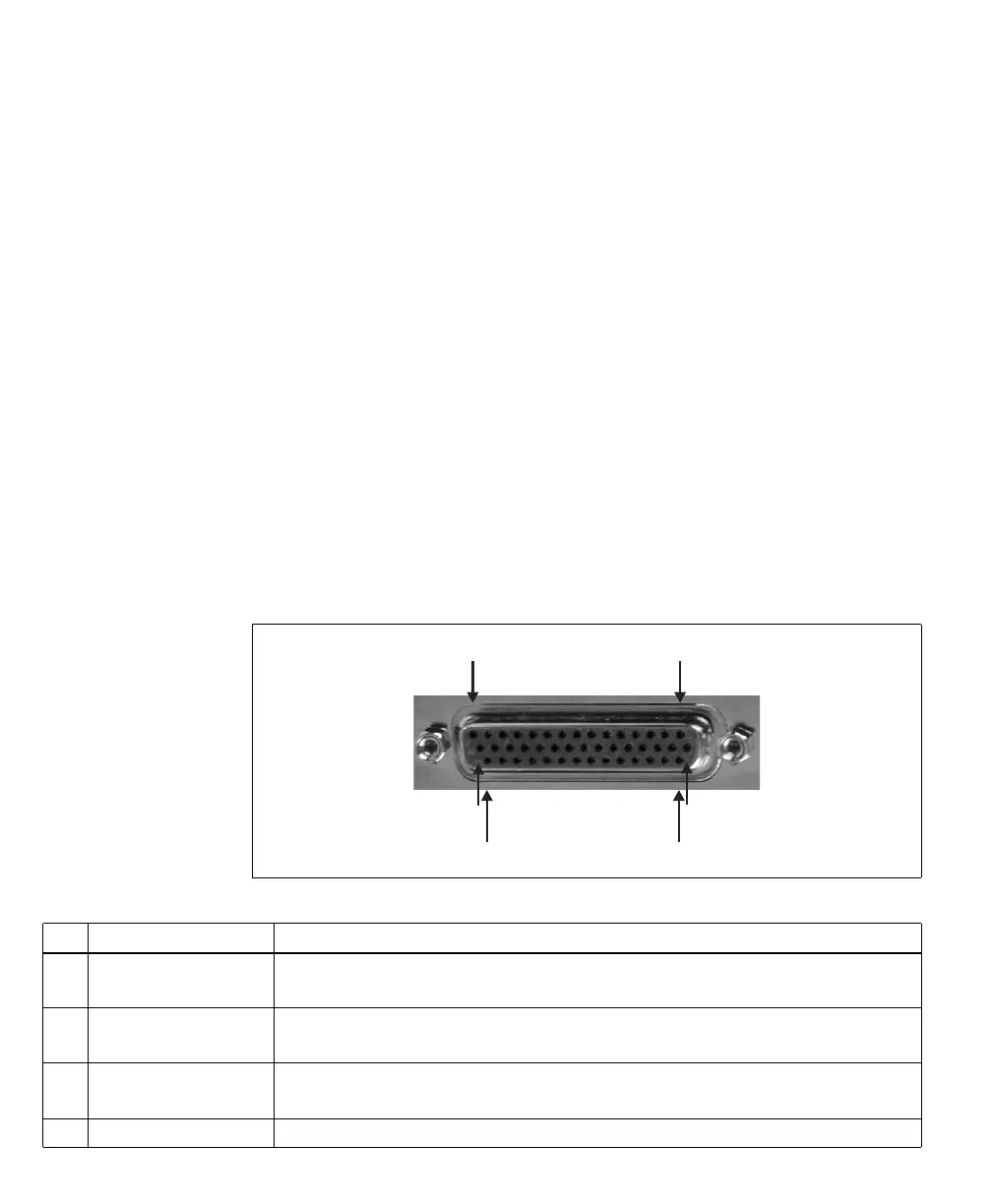
The external auxiliary I/O connector is an HD-44 female connector, located on
the auxiliary I/O adapter bracket. It interfaces with the 30-pin internal auxiliary
I/O connector on the board, making the I/O signals accessible outside the
computer enclosure.
The pinout for this connector is as follows. The description of each (positive)
auxiliary signal states whether the signal is specific to an independent acquisition
path and the type of signals that can be routed onto it.
16
31
15
30
44
Pin Signal Description
1 AUX(TRIG)_OPTO_IN0+ Opto-isolated auxiliary 0 (input) for an unspecified acq. path (positive).
Supported signals: timer-trigger input 0, timer-clock input 0, user-defined 0 (input).
2 AUX(TRIG)_OPTO_IN1- Opto-isolated auxiliary 1 (input) for an unspecified acq. path (negative).
See pin 31 for more information.
3 AUX(TRIG)_OPTO_IN3+ Opto-isolated auxiliary 3 (input) for an unspecified acq. path (positive).
Supported signals: timer-trigger input 3. timer-clock input 3, user-defined 3 (input).
4GND Ground.