142 Appendix B: Technical information
Analog video input connectors
The two analog video input connectors are DVI dual-video-input female
connectors. They are used to receive video input signals and transmit/receive
timing, synchronization, and communication signals between the video source
and the frame grabber.
Important To connect the output of a display board (with a DVI output connector) to the
analog video input connectors, you can use a standard cable (DVI-I to DVI-I or
DVI-A to DVI-A cable) if the display board encodes the synchronization signals
on the video data (sync on green). Otherwise, you must use the Matrox
DVI-TO-8BNC/O cable or a custom cable that re-routes the synchronization
signals to the appropriate pins.
Note that synchronization and clock signals can be either LVDS or TTL; when
TTL, they are expected on the pin denoted as positive.
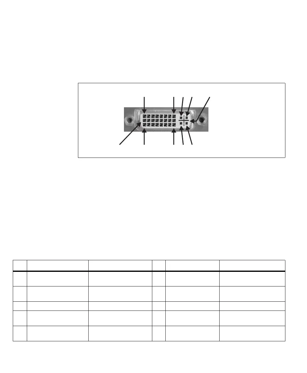
The pinout for DVI connector 0 is as follows:
C2
C5,C6,M1,M2
C1
C4C3
8
24
1
17
9
Pin Signal
1
Description Pin Signal
1
Description
1 P1_LVDS/TTL_VSYNC_IO- VSYNC input/output for acq.
path 1 (negative).
17 P1_LVDS/TTL_CLK_IO- Clock input/output for acq.
path 1 (negative).
2 P1_LVDS/TTL_VSYNC_IO+ VSYNC input/output for acq.
path 1 (positive).
18 P1_LVDS/TTL_CLK_IO+ Clock input/output for acq.
path 1 (positive).
3 GND Ground. 19 GND Ground.
4 P0_LVDS/TTL_VSYNC_IO- VSYNC input/output for acq.
path 0 (negative).
20 P0_LVDS/TTL_CLK_IO- Clock input/output for acq.
path 0 (negative).
5 P0_LVDS/TTL_VSYNC_IO+ VSYNC input/output for acq.
path 0 (positive).
21 P0_LVDS/TTL_CLK_IO+ Clock input/output for acq.
path 0 (positive).