Matrox Solios GigE acquisition section 89
Supported functionality
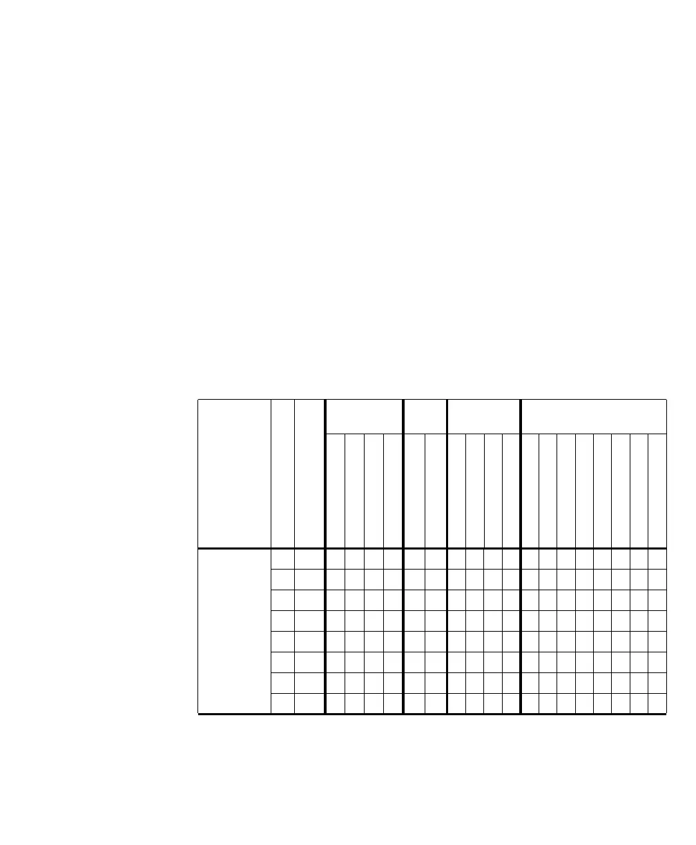
The following table summarizes the functionality that the auxiliary I/O controller
supports; that is, the synchronization, timing, and control signals that the
controller can receive/generate. These signals are available by defining an auxiliary
signal as the required synchronization, timing, or control signal. For example,
AUX(TRIG)_TTL_IO_6 can be defined as exposure output signal 0 to 7,
timer-trigger input signal 6, timer-clock input signal 6, or user-defined signal 6,
for any acquisition path.
Notice that exposure signals are not restricted to a specific auxiliary output signal.
For example, any auxiliary output signal, or auxiliary I/O signal in output mode,
can be set to exposure output signal 0.
Note that for Matrox Solios GigE, the synchronization, timing, and control signals
are not dependent on an acquisition path, and by extension, neither are the
auxiliary signals.
Type of
signal
Signal number
In/Out
OPTO aux. in LVDS
aux. in
TTL aux. I/O TTL aux. out
AUX(TRIG)_OPTO_IN0
AUX(TRIG)_OPTO_IN1
AUX(TRIG)_OPTO_IN2
AUX(TRIG)_OPTO_IN3
AUX(TRIG)_LVDS_IN4
AUX(TRIG)_LVDS_IN5
AUX(TRIG)_TTL_IO_6
AUX(TRIG)_TTL_IO_7
AUX(TRIG)_TTL_IO_8
AUX(TRIG)_TTL_IO_9
AUX(EXP)_TTL_OUT10
AUX(EXP)_TTL_OUT11
AUX(EXP)_TTL_OUT12
AUX(EXP)_TTL_OUT13
AUX(EXP)_TTL_OUT14
AUX(EXP)_TTL_OUT15
AUX(EXP)_TTL_OUT16
AUX(EXP)_TTL_OUT17
Exposure
output
0 Out xxxxxxxxxxxx
1 Out xxxxxxxxxxxx
2 Out xxxxxxxxxxxx
3 Out xxxxxxxxxxxx
4 Out xxxxxxxxxxxx
5 Out xxxxxxxxxxxx
6 Out xxxxxxxxxxxx
7 Out xxxxxxxxxxxx