1 - 10 System Map: Front & Top Views
Quick Start Guide
1
System Map: Front & Top Views
Figure 1 - 4
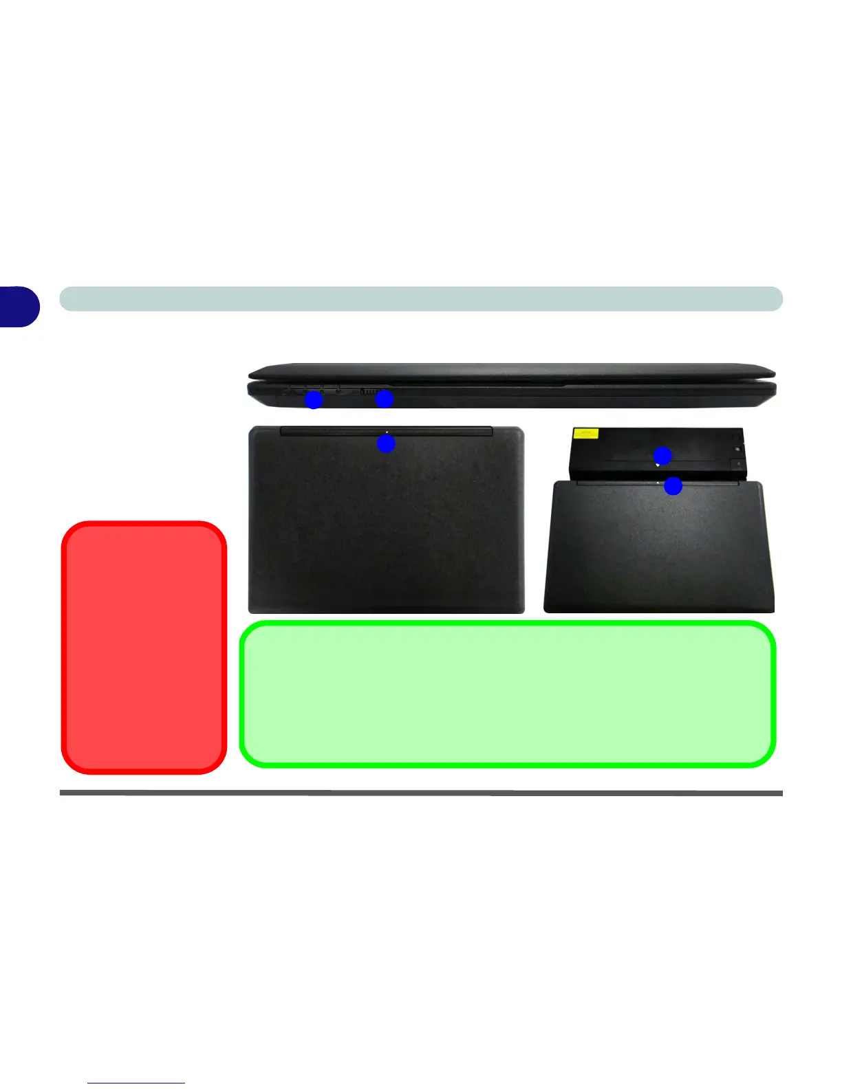
Front & Top Views
(with Optional
Docking Station)
1. LED Indicators
2. WLAN Switch
3. Docking Station
(Optional)
4. Alignment
Markers
WLAN Switch
Use the WLAN Switch (for
Wireless LAN only) to tog-
gle power to the WLAN
module. The position of the
WLAN switch governs the
power status of the WLAN
module at startup, and upon
resuming from a power sav-
ing state (see
“Wireless
LAN Switch” on page 7
- 11
).
Docking
If your purchase includes the docking station, align the markers on the top case of the computer with
that on the docking station before docking (see the accompanying docking station for full details of the
docking procedure). If your purchase does not include the docking station, the marker will still appear
on the computer’s top case but may be disregarded.
3
4
4
1
2