24
11921 Slauson Ave. Santa Fe Springs, CA. 90670 (800) 227-4116 FAX (888) 771-7713
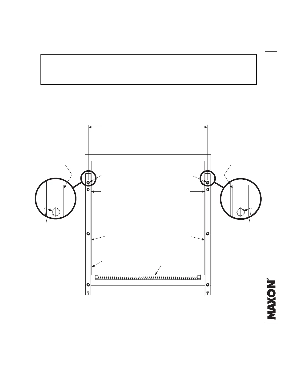
91-1/4” + 3/16” / - 1/16” (96” WIDE VEH)
96-1/4” + 3/16” / - 1/16” (102” WIDE VEH)
(DIMENSIONS TAKEN FROM
CENTER OF EACH TOP HANGER)
87-1/4” + 3/16” / - 1/16” (96” WIDE VEH)
92-1/4” + 3/16” / - 1/16” (102” WIDE VEH)
(DIMENSIONS TAKEN FROM INNER EDGE
OF MOUNTING BRACKETS)
LH MOUNTING
PLATE
FIG. 24-1A
FIG. 24-1
RH MOUNTING
PLATE
FIG. 24-1B
3. Position LH mounting plate on vehicle body as shown in
FIGS. 24-1, 24-1A, and 24-1B.
EXTENSION PLATE
STEP 3 - POSITION LIFTGATE - Continued
NOTE: Installer can use either set of dimensions shown in FIG. 24-1 to install RH
mounting plate. The fi rst set of dimensions is taken from the center of each
hanger, and the second set of dimensions is taken from the inner edge of
the mounting plates.
TOP HANGER
TOP HANGER TOP HANGER
TOP HANGER
RH MOUNTING
PLATE
LH MOUNTING
PLATE
INNER EDGE INNER EDGE
VEHICLE
BODY
METHOD 1 - PRE-INSTALL MOUNTING PLATES
AND EXTENSION PLATE ON VEHICLE - Continued
 Loading...