Setup
Connections
EPOS4 50/5 Hardware Reference
CCMC | 2023-07 | rel11726
3-21
3.3.2 Logic Supply (X2)
Separate power supply
The logic part of the controller may be supplied by a separate supply voltage provided that it meets the
below stated minimum requirement:
If not supplied separately, the logic supply is internally connected to the power supply.
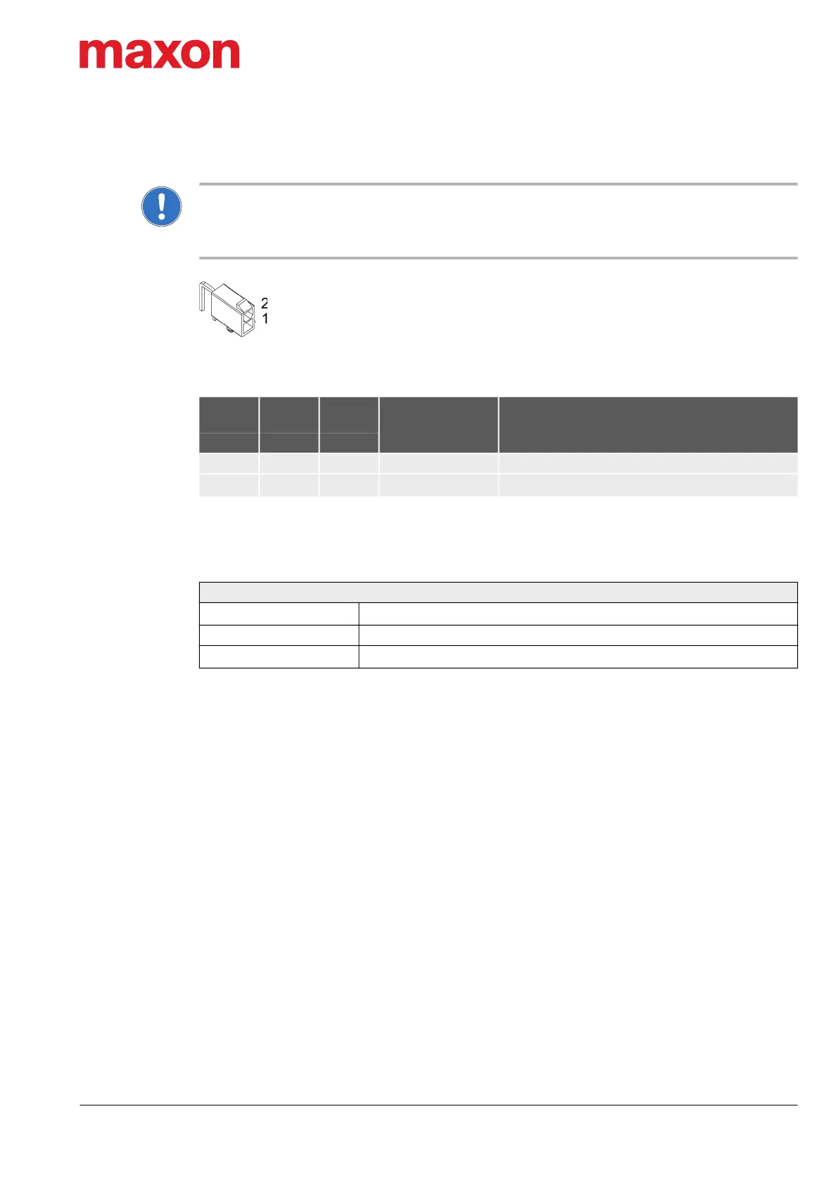
Figure 3-7 Logic supply connector X2
Table 3-13 Logic supply connector X2 – Pin assignment
For the matching prefab cable assembly Table 3-11.
Table 3-14 Logic supply requirements
X2
Head A
Prefab
Cable
Head B
Signal Description
Pin Color Pin
1 black − GND Ground
2 black +
+V
C
Logic supply voltage (+10…+50 VDC)
Power supply requirements
Output voltage
+V
C
10…50 VDC
Absolute supply voltage min. 8 VDC; max. 56 VDC
Min. output power
P
C
min. 3.5 W
 Loading...