Setup
Connections
EPOS4 50/5 Hardware Reference
CCMC | 2023-07 | rel11726
3-23
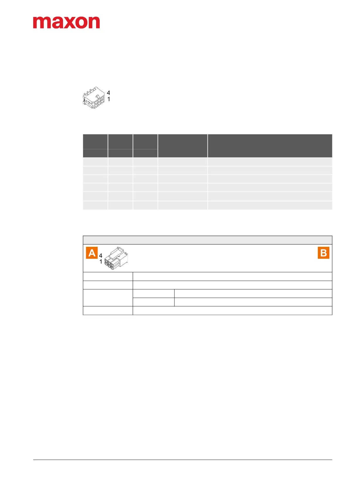
3.3.4 Hall Sensor (X4)
Suitable Hall effect sensors IC use «Schmitt trigger» with open collector output.
Figure 3-9 Hall sensor connector X4
Table 3-18 Hall sensor connector X4 – Pin assignment
Table 3-19 Hall Sensor Cable
Continued on next page.
X4
Head A
Prefab
Cable
Head B
Signal Description
Pin Color Pin
1 green Hall sensor 1 Hall sensor 1 input
2 brown Hall sensor 2 Hall sensor 2 input
3 white Hall sensor 3 Hall sensor 3 input
4 yellow GND Ground
5 grey
V
Sensor
Sensor supply voltage (+5 VDC; I
L
100 mA)
6 black Hall shield Cable shield
Hall Sensor Cable (275878)
Cross-section
5 x 0.14 mm
2
, shielded, grey
Length 3 m
Head A
Plug Molex Micro-Fit 3.0, 6 poles (430-25-0600)
Contacts Molex Micro-Fit 3.0 female crimp terminals (430-30-xxxx)
Head B
Wire end sleeves 0.14 mm
2