Setup
Status Indicators
EPOS4 50/5 Hardware Reference
CCMC | 2023-07 | rel11726
3-59
3.4 Status Indicators
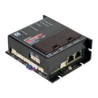
The EPOS4 features three sets of LED indicators to display the device condition.
A NET Status; the LEDs display communication RUN states and errors conditions
B Device Status; the LEDs display the device’s operation status and error conditions
C NET Port; the LED displays the NET link activity
For detailed information see separate document «EPOS4 Firmware Specification».
Figure 3-46 LEDs – Location
3.4.1 NET Status
The LEDs (Figure 3-46; A) display the actual status and possible errors of the EPOS4 in respect to the
NET network:
• Green LED shows the RUN state
• Red LED indicates errors
Table 3-71 NET Status LEDs
LED
Description
Green Red
OFF — EPOS4 is in state INIT
Blink — EPOS4 is in state PRE-OPERATIONAL
Single flash — EPOS4 is in state SAFE-OPERATIONAL
ON — EPOS4 is in state OPERATIONAL
Flicker — EPOS4 is in state BOOTSTRAP
— OFF EPOS4 is in operating condition
— Double flash
An application watchdog timeout has occurred
Example: Timeout of Sync Manager Watchdog
— Single flash
EPOS4 has changed the COM state due to an internal error
Example: Change of state “Op” to “SafeOpError” due to Sync Error
— Blink
General Configuration Error
Example: State change commanded by master is not possible due to
actual settings (register, object, hardware configuration)
Blink = continuous blinking (2.5 Hz)
Flash = flashing (0.2 s), followed by pause of 1 s
Flicker = continuous flickering (10Hz)