Setup
Connections
EPOS4 50/5 Hardware Reference
CCMC | 2023-07 | rel11726
3-43
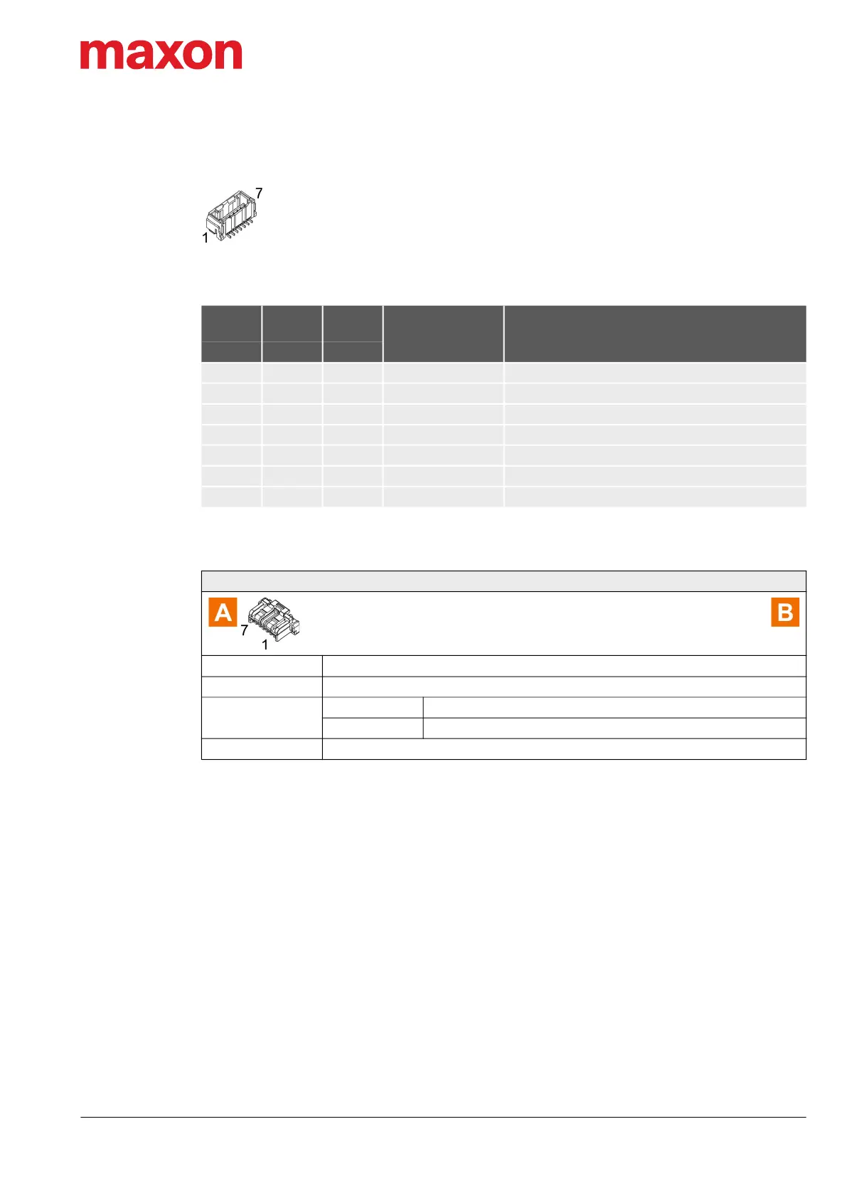
3.3.8 Analog I/O (X8)
Figure 3-32 Analog I/O connector X8
Table 3-42 Analog I/O connector X8 – Pin assignment
Table 3-43 Signal Cable 7core
Continued on next page.
X8
Head A
Prefab
Cable
Head B
Signal Description
Pin Color Pin
1 white 1 AnIN1+ Analog input 1, positive signal
2 brown 2 AnIN1− Analog input 1, negative signal
3 green 3 AnIN2+ Analog input 2, positive signal
4 yellow 4 AnIN2− Analog input 2, negative signal
5 grey 5 AnOUT1 Analog output 1
6 pink 6 AnOUT2 Analog output 2
7 blue 7 GND Ground
Signal Cable 7core (520854)
Cross-section
7 x 0.14 mm
2
, grey
Length 3 m
Head A
Plug Molex CLIK-Mate, single row, 7 poles (502578-0700)
Contacts Molex CLIK-Mate crimp terminals (502579)
Head B
Wire end sleeves 0.14 mm
2