Setup
Connections
EPOS4 50/5 Hardware Reference
3-28 CCMC | 2023-07 | rel11726
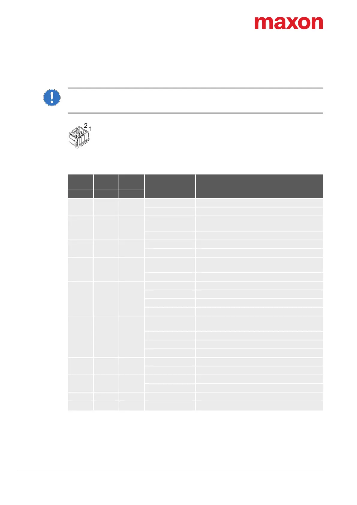
3.3.6 Sensor (X6)
Additional sensors, both incremental and serial encoders, can be connected.
Check on the applied sensor’s data sheet
If the specified inrush current or the maximum continuous current of the sensor should exceed 145 mA, you
can connect the sensor supply voltage (V
Sensor
) in parallel to the auxiliary output voltage (V
Aux
).
Figure 3-14 Sensor connector X6
Table 3-26 Sensor connector X6 – Pin assignment
Continued on next page.
X6
Head A
Prefab
Cable
Head B
Signal Description
Pin Color Pin
1 white 1
Channel A Digital/analog incremental encoder channel A
HsDigIN1 High-speed digital input 1
2 brown 2
Channel A\
Digital/analog incremental encoder channel A
complement
HsDigIN1\ High-speed digital input 1 complement
3 green 3
Channel B Digital/analog incremental encoder channel B
HsDigIN2 High-speed digital input 2
4 yellow 4
Channel B\
Digital/analog incremental encoder channel B
complement
HsDigIN2\ High-speed digital input 2 complement
5 grey 5
Channel I Digital/analog incremental encoder channel I
HsDigIN3 High-speed digital input 3
Clock Clock (SSI)
HsDigOUT1 High-speed digital output 1
6 pink 6
Channel I\
Digital/analog incremental encoder channel I
complement
HsDigIN3\ High-speed digital input 3 complement
Clock\ Clock (SSI) complement
HsDigOUT1\ High-speed digital output 1 complement
7 blue 7
Data Data (SSI)
HsDigIN4 High-speed digital input 4
8 red 8
Data\ Data (SSI) complement
HsDigIN4\ High-speed digital input 4 complement
9 black 9 GND Ground
10 violet 10
V
Aux
Auxiliary output voltage (+5 VDC; I
L
145 mA)