Setup
Connections
EPOS4 50/5 Hardware Reference
CCMC | 2023-07 | rel11726
3-25
3.3.5 Encoder (X5)
Best practice
• Differential signals offer good resistance against electrical interference. Therefore, we recommend
using a differential scheme. Nevertheless, the controller supports both schemes – differential and sin-
gle-ended (unsymmetrical).
• For best performance, we strongly recommend using encoders with a line driver. Otherwise, limita-
tions may apply due to slow switching edges.
• Even though 2-channel will do, we strongly recommend to use only 3-channel versions.
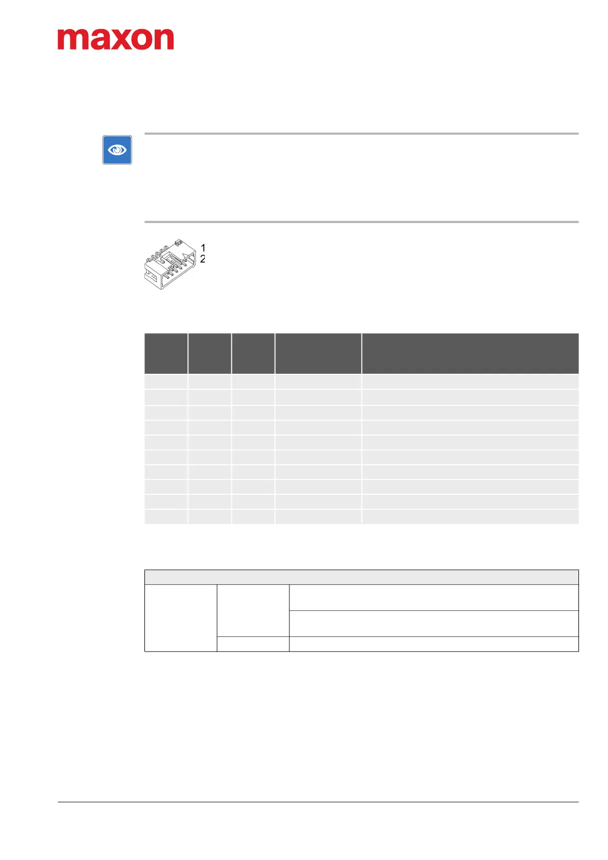
Figure 3-11 Encoder connector X5
Table 3-21 Encoder connector X5 – Pin assignment
Table 3-22 Encoder connector X5 – Accessories
Continued on next page.
X5
Head A
Prefab
Cable
Head B
Signal Description
Pin Color Pin
1 brown 1 – not connected
2 white 2
V
Sensor
Sensor supply voltage (+5 VDC; I
L
100 mA)
3 red 3 GND Ground
4 white 4 – not connected
5 orange 5 Channel A\ Channel A complement
6 white 6 Channel A Channel A
7 yellow 7 Channel B\ Channel B complement
8 white 8 Channel B Channel B
9 green 9 Channel I\ Channel I complement
10 white 10 Channel I Channel I
Accessories
Suitable strain
relief
Retainer
For sockets with strain relief:
1 retainer clip, height 13.5 mm, 3M (3505-8110)
For sockets without strain relief:
1 retainer clip, height 7.9 mm, 3M (3505-8010)
Latch For sockets with strain relief: 2 pieces, 3M (3505-33B)
 Loading...