Installation and Wiring
7
SECTION 1 2 3 4 5 6 7 8 9 10 11 12 13 14 15 16
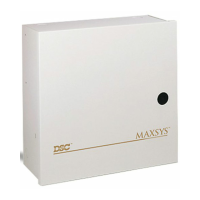
2.12 Bell Output Wiring (BELL
+
and BELL
-
)
These terminals are used for powering
bells, sirens or other devices requiring
steady output voltage on alarm. The panel
can provide up to 2A short-term or 700mA
long-term current. The output is super
-
vised. A trouble condition will be gener-
ated when the bell connection is lost. If no
bell or siren is being used, connect a 1000
resistor across the BELL+ and BELL- ter
-
minals to eliminate a trouble condition.
To ensure proper operation, the wire length
of the bell loop must be considered.
Consult the following chart to determine the maximum wire
length for the bell loop with respect to current. The values reflect
the use of a 30 watt siren.
To increase the length, double up on wire. For example, when
using 22-gauge quad, use two conductors for the Bell+ connection
and two for the Bell-. This effectively doubles the maximum dis
-
tance.
For UL residential installations, when a bell or siren is used for
fire signaling with a pulsed cadence, it must be connected
between the AUX+ and BELL- terminals. To maintain bell circuit
supervision, do not connect more than one device to the BELL-
terminal. A fire bell or siren used for this application must be UL
Listed and have a current consumption of 400mA or less (e.g.
Wheelock MT-12/24-R).
NOTE: For Commercial Fire applications, you must use the ‘CF’
version of the panel and the PC4702BP.
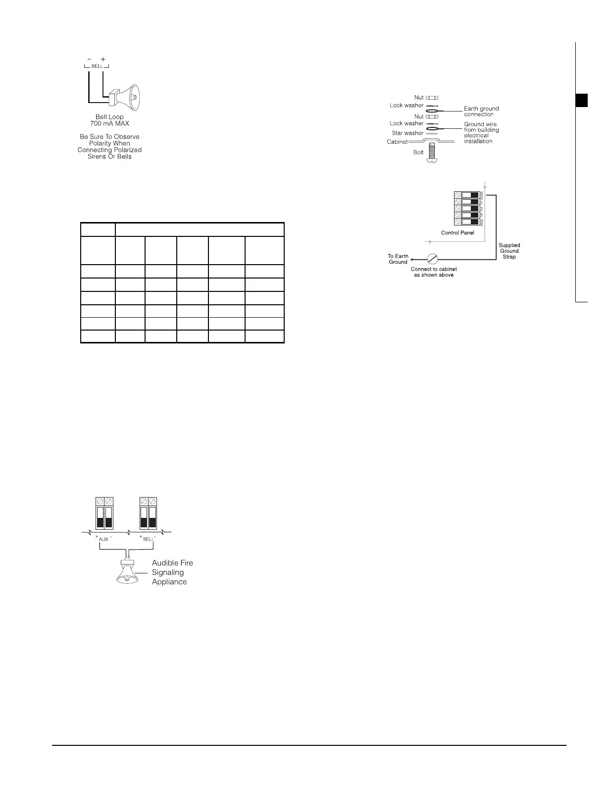
2.13 Earth Ground Wiring
The cabinet should be earth grounded using the grounding kit
supplied. Ensure that the connection from the cabinet to the
metallic cold water pipe or earth grounding rod is made with min
-
imum 14-gauge solid copper wire.
The EGND terminal must be connected to earth ground to enable
ground fault detection. A Ground Fault trouble will be indicated if
any conductor on the system has a resistance to earth ground of
40k or less.
Only earth ground the main panel and the first module connected
to the telephone line.
2.14 Applying Power (AC and Battery)
WARNING:: Do not connect the battery or transformer until all
other wiring is complete.
Battery Connection – Red & Black Battery Leads
Connect the red battery lead to the positive terminal of the battery
and the black lead to the negative terminal.
WARNING:: Observe the correct polarity. If the battery is connected
backwards, the panel will not operate.
AC Power Terminals
WARNING:: Connect the battery before connecting the AC.
A 16V, 40 VA transformer connected to an unswitched AC power
source should be wired to these terminals.
To achieve the rated outputs as previously described, the AC input
must be connected to the secondary of a transformer rated at 16
VAC, 40VA minimum. The transformer is not supplied with the
equipment and must be mounted outside the cabinet. Do not con
-
nect the transformer primary to an outlet that is controlled by a
switch.
The control panel monitors the presence of AC. Upon the loss of
AC power a trouble condition will be generated. The keypad trou
-
ble light will turn on. If programmed, the keypad will also beep.
For more information regarding AC options, see
10.1 ”AC/DC
Power Options’.
Applying Power to the Main Panel
Once all field wiring has been completed and checked for opens,
shorts and grounds, power can be applied to the panel as follows:
1. Connect the battery leads.
2. Connect the AC transformer.
The panel will not power up correctly if AC power is applied
before the battery is connected.
Battery Selection Charts
The charts below are to determine the battery required to support
the main panel for either 24 hours or 60 hours in the standby
mode. The battery size is measured in amp hours (Ah). To deter
-
mine the appropriate battery size, perform the following:
1. Calculate the total current required when the panel is not in
alarm. This is the standby current. See section 2.4 for further
information on current calculation.
2. Determine the current that will be drawn when the panel is in
alarm.
3. On the chart below, find the standby current on the horizontal
axis and the alarm current on the vertical axis.
Di st a n ce t o l a st b e l l / si re n ( f t / m)
Bell Loop
Loa d
Cur re nt
22 AWG
Wire
20 AWG
Wire
18 AWG
Wire
16 AWG
Wire
14 AWG
Wire
2000mA 18/6 29/9 46/14 73/22 116/35
1800mA 20/6 32/10 51/16 81/25 129/39
1000mA 36/11 58/17 92/28 147/44 233/70
700mA 52/16 82/25 132/40 210/64 332/101
500mA 73/22 115/35 184/56 293/89 465/141
100mA 364/110 577/175 922/279 1467/445 2326/705
Tighten nut to break paint and make
good connection to the cabinet