8
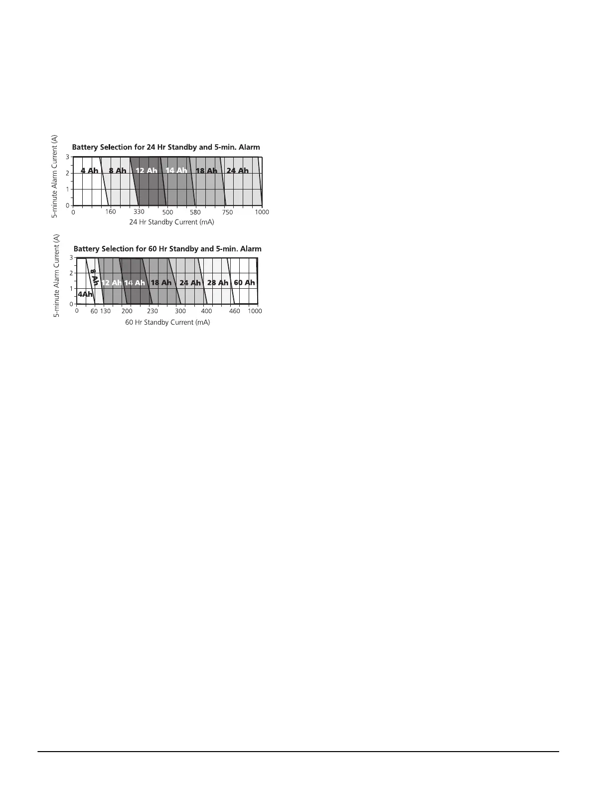
4. Find the region of the chart where the standby current and the
alarm current values intersect. The region corresponds to the
required battery Ah capacity.
For example:
Standby current = 500 mA
Alarm current = 2 A
On the 24Hr chart, the battery capacity required is 14Ah.
2.15 Lithium Batteries
The PC4020 circuit board includes a lithium battery (please see
the wiring diagram on page ii.) This battery is not replaceable.
There is a danger of explosion if the battery is incorrectly
replaced.
If the lithium battery stops working, return the circuit board to
your distributor. Batteries may cause a fire when in contact with
metal. If you need to dispose of the circuit board and/or the lith
-
ium battery, wrap the battery in non-conductive tape. Check with
your local government for battery disposal regulations.
WARNING: Do not store the batteries in such a way that they come
into contact with each other or with any piece of metal. Explosion or
fire may occur. Should fire occur, use only dry chemical fire extin-
guishers. Do not use water to put out the fire.
Do not heat the batteries. Do not dispose of the batteries or circuit
boards in a fire. Do not disassemble the batteries. Do not apply pres-
sure to or deform the batteries. Ensure that the above precautions are
strictly observed by related departments, including, but not limited to,
production, sales and outside contractors.
*NOTE:
For installation in Brazil, the control panel shall use one ferrite Stew-
ard P/N 28A2024-0A0 on the battery leads (loop wires with one turn)
and one ferrite Steward P/N 28A2024-0A0 on the keybus cable con-
nected to the LCD4501 keypad (loop wires with two turns).