Grade AA Central Station (using T-Link)
Household Fire and Grade A Household Burglary
Grade A Local
Grade B Central Station and Grade A Police
Connect with basic line security
Grade C Central Station and Grade A Police
Connect with basic line security
Local, Central and Remote Station Fire Monitoring
Type of signalling: DACT, RF
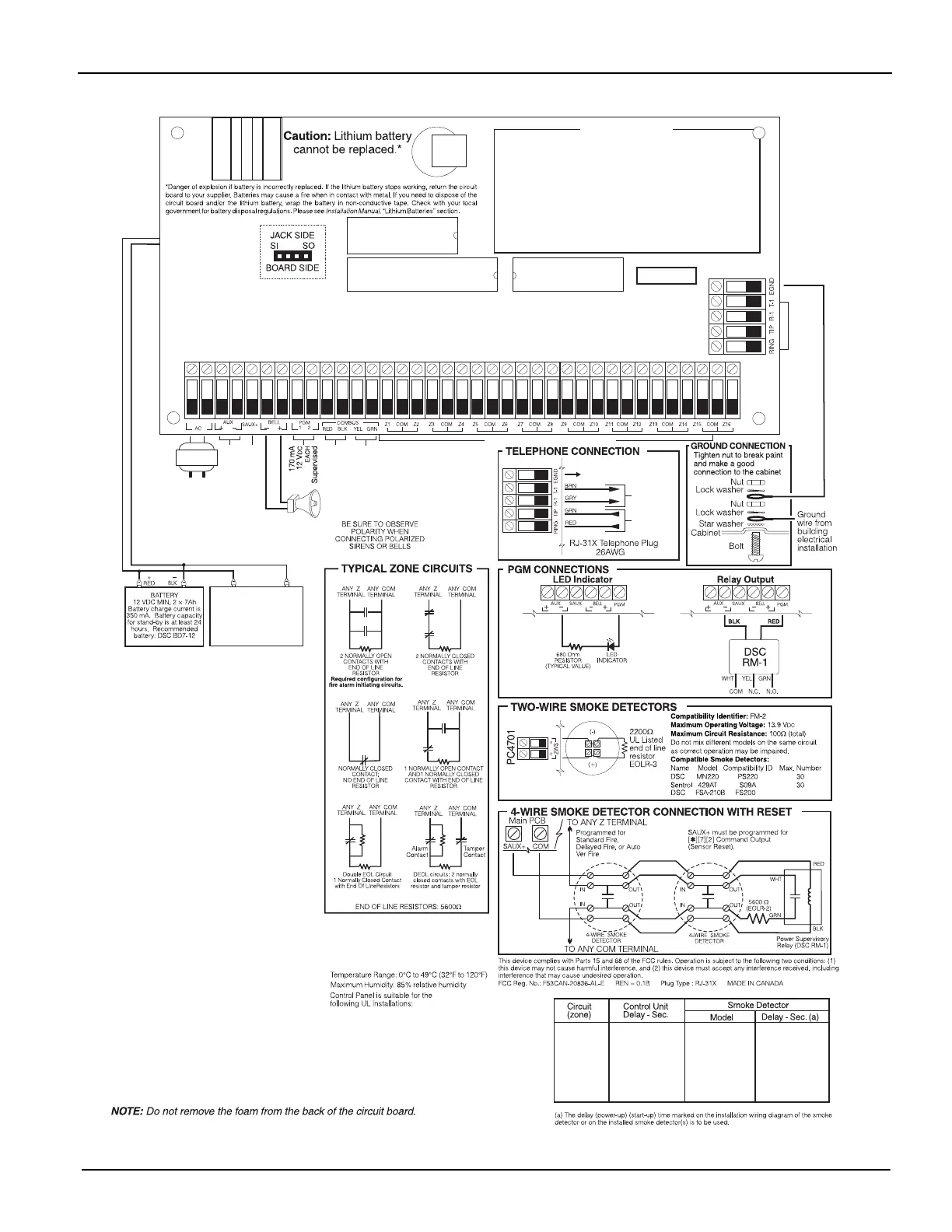
WARNING: All circuits are classified for UL Installation as Power Limited/Class 2 Power Limited,
except for the battery leads, which are not Power Limited. Please see the Installation Manual
Section 2, Installation & Wiring. A minimum 1/4" (6.4mm) separation must be maintained at all
points between Power Limited and all other non-Power Limited wiring. Do not route any wiring
over circuit boards. Maintain at least 1" (25.4mm) separation.
UL LISTED
Do not connect transformer to
receptacle controlled by a switch.
The transformer must have
a restraining means.
UL Listed Class II
Transformer
120V
AC
60Hz, Primary
Recommend DSC PTD 1640U
NOTE: For the PC4020CF, the transformer
is provided with the product.
BELL LOOP
700mA, 12 VDC
Supervised for
non-fire use only
300mA, 12VDC
Supervised
500mA, 12VDC
Supervised
300mA, 5VDC
Supervised
500mA, 12VDC
Supervised
Combus to all Modules
Refer to Installation Manual for
detailed information on wiring
To Ground Connection
Out to
equipment
on premises
Incoming line
from phone
company
WARNING
High Voltage. Disconnect AC power
and telephone lines prior to servicing.
Incorrect connections may result in
improper operation. Inspect wiring
and ensure connections are correct
before applying power.
UA016
Supervised
8 VDC Nominal @ 1mA Supervised
16.5V@40VA
Secondary
For remote station use, connect PS4350
with 60h battery standby capacity.
NOTE: Battery backup
requirements will vary.
Please refer to
'Battery Standby Calculation
Charts' (#29003350)
for more information
*
* See Smoke Detector Manual part# 29006015
Printed information describing proper installation, operation,
testing, maintenance, evacuation planning, and repair service is to
provided with this equipment.
Security detection devices that require power from the control
panel must be UL Listed for the intended application and operate
over the range of 10.0 to 14.0 VDC. The DSC Bravo Series is a
recommended UL Listed motion detector.
Refer to the Installation Manual P/N 29007011, Instruction Manual
P/N 29007014 for complete operating instructions.
The PC4020 is UL Listed for limited energy installations per NEC
Article 760. Recognized limited energy cable should be used.
Observe NEC wiring requirements and local codes dened by the
authority having jurisdiction.