Service Manual 800 series Rev. 1/01.07.2019
9
Medisoft RAM Italia S.r.l. - All rights reserved
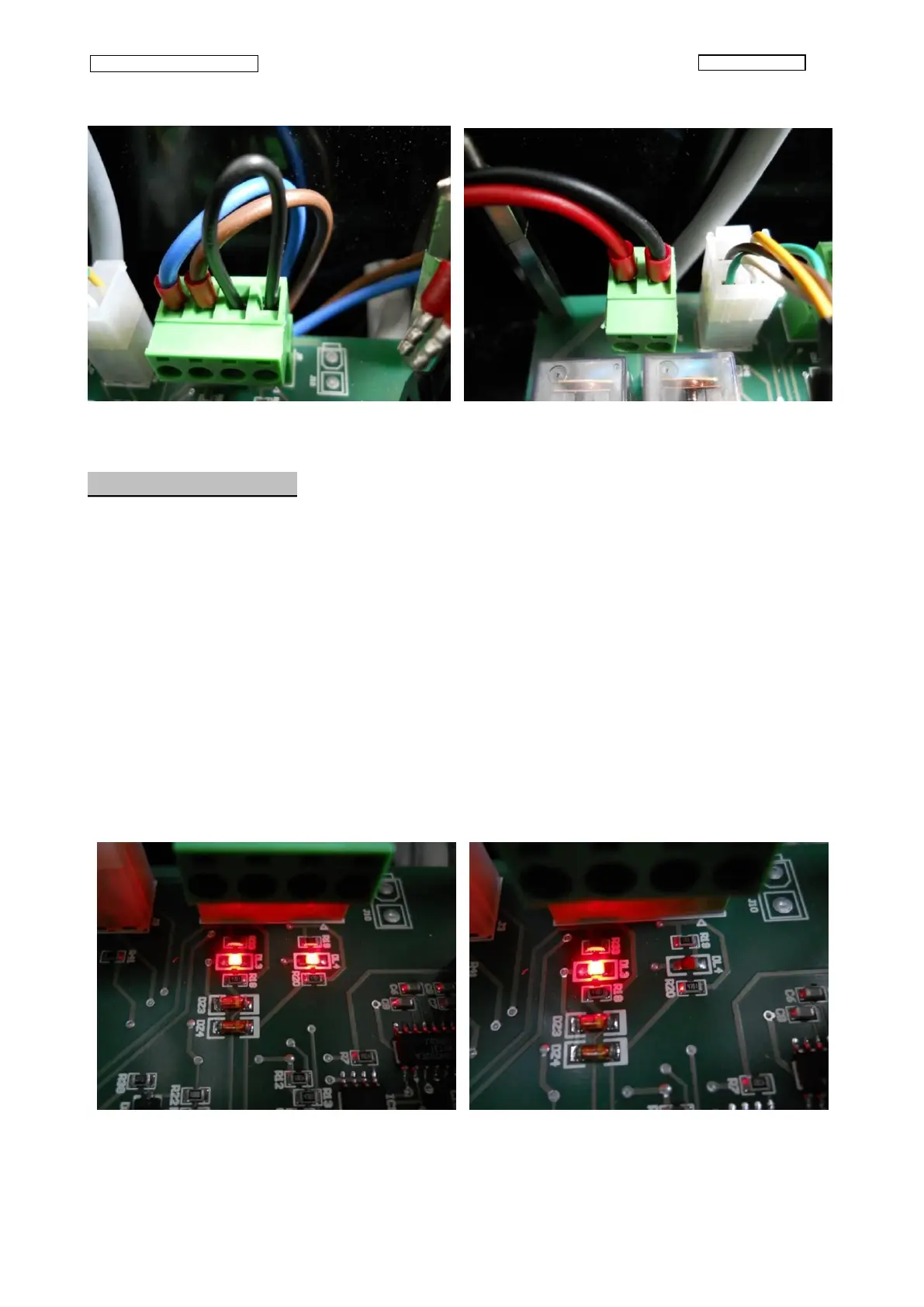
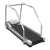
Fig.8 Fig.9
3.12 - Test limit switch
Tools needed :
• Small screwdriver.
• Multi meter
With the help of the multi meter, check the operation of the switches, verifiable on the J8 connector
screws (with clamp screws face view, the two on right are keyed to the switch mounted on the
beam, the two on the left correspond to the switch mounted on aluminium bracket).
These switches should be "normally closed".
If pushing the switch they open the contact the test is OK, otherwise it is not OK.
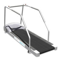
NOTE: The operation of the switches will be highlighted during the normal operation of the
treadmill by LEDs DL3 and DL4 (Fig. 10), who not lit after their activation (LED DL4 will go off
when the treadmill is at 0% elevation) (Fig. 11).
Fig.10 Fig.11