190
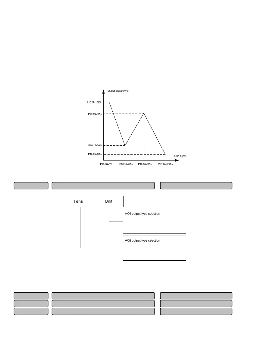
8) P10.18=8÷20×100%=40.0%, set the percentage of the inflection point 1 of the curve 1 reference
(8kHz) relative to 20kHz (P09.11);
9
) P10.19=10.00Hz÷P02.15 x100%, set the corresponding set frequency percentage of the inflection
point 1 of the curve 1 reference (8kHz pulse signal);
10
) P10.20=1÷20×100%=5.0%, set the percentage of the minimum reference of curve 2 (1kHz)
relative to 20kHz (P14.13);
11
) P10.21=50.00Hz÷P02.15 x100%, set the corresponding set frequency percentage of the minimum
reference (1kHz pulse signal);
Fig. 6-52 Example of parameter setting for pulse signal input
10V~0:0
)20mA~0(or
10V~0:0
)20mA~0(or
10V~2:1
)20mA~4(or
10V~2:1
)20mA~4(or
Fig. 6-53 Analog output type selection
This function code is used for selecting the analog output range of AO1 and AO2. For the voltage or
current output, it shall be determined by the jumper on the terminal board. For details, please refer to the
description of the terminal board.
The linear correspondence relationship between the AO1 and AO2 output and the indication range is as
shown in Table 6-14.
AO1zero offset correction -100.0%~100.0%
0.0%
P10.25
AO1
ain 0.0~200.0%
100.0%
P10.24
Analo
out
ut terminal AO1 function 0~26
00
P10.23
Analo
out
ut t
e 0~11H
00
P10.22
 Loading...