2C-6 - ELECTRICAL 90-830234R3 DECEMBER 1997
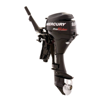
8. Place roller of cam follower against throttle cam
and adjust idle stop screw to align raised mark of
throttle cam with center of cam follower roller.
Tighten locknut.
53432
a
b
b
b
c
e
f
g
d
a - Cam Follower Adjustment Screw
b - Synchronizing Screws
c - Throttle Arm
d - Idle Stop Screw
e - Roller
f - Throttle Cam
g - Locknut
9. Holding throttle arm at idle position, adjust cam
follower so that a clearance of 0.005 in. - 0.020 in.
(0.13mm - 0.51mm) exists between roller and
throttle cam. Tighten screw securing cam
follower.
53433
0.005 – 0.020
a
b
c
(0.13 – 0.51mm)
a - Roller
b - Throttle Cam
c - Screw
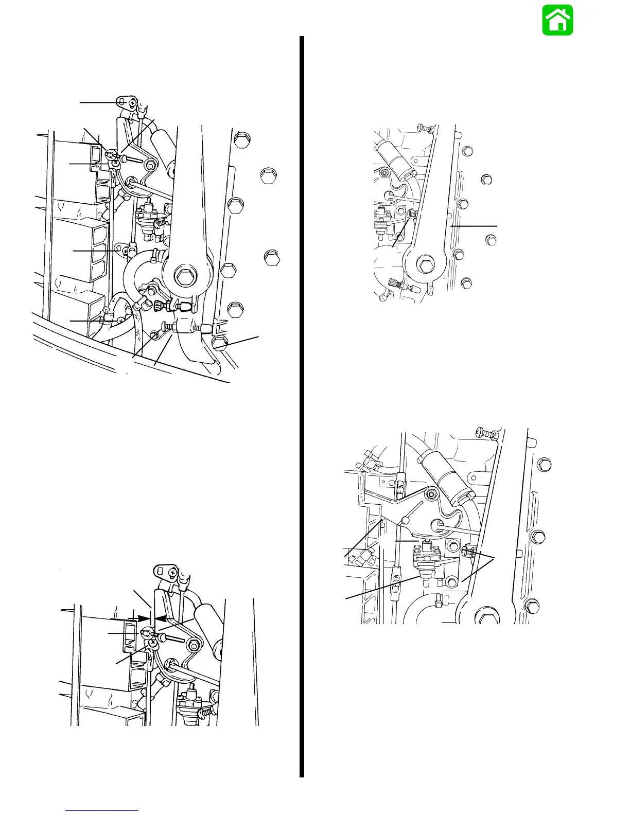
10. Hold throttle arm against full throttle stop. Adjust
full throttle stop screw to allow throttle shutters to
open fully. To prevent throttle shutters to act as a
stop, screw in stop screw until there is a gap of
0.015 in. (0.40mm) between roller of cam follow-
er and throttle lever.
53430
a
b
a - Throttle Arm
b - Full Throttle Stop Screw
11. Hold throttle cam in full throttle position. If neces-
sary adjust acceleration pump adjusting bolts
position so that a gap of 0.030 in. (0.76mm) exists
between throttle cam and top of acceleration
pump aluminum housing.
53429
a
b
c
d
a - Throttle Cam
b - Bolts
c - 0.030 in. (0.76mm) Gap
d - Accelerator Pump
 Loading...