90-830234R3 DECEMBER 1997 MID-SECTION - 5C-41
9. Remove shock rod assembly from vise.
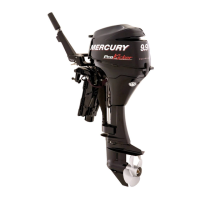
10. Install ball, seat, and spring (five sets) to shock
rod piston.
11. Secure components with plate. Torque screws to
35 lb. in. (4.0 N·m).
a
c
d
e
b
51147
a - Screw (3) Torque to 35 lb. in. (4.0 N⋅m)
b - Plate
c - Spring (5)
d - Seat (5)
e - Ball (5)
Shock Rod Installation
1. Place trim cylinder in soft jawed vice.
2. Install lubricated O-ring to memory piston and
place into cylinder. Push memory piston all the
way to bottom.
b
a
a - Memory Piston
b - O-ring
3. Fill cylinder three inches (76.2mm) from top of
cylinder using Quicksilver Power Trim and Steer-
ing Fluid. If not available, use automotive (ATF)
automatic transmission fluid.
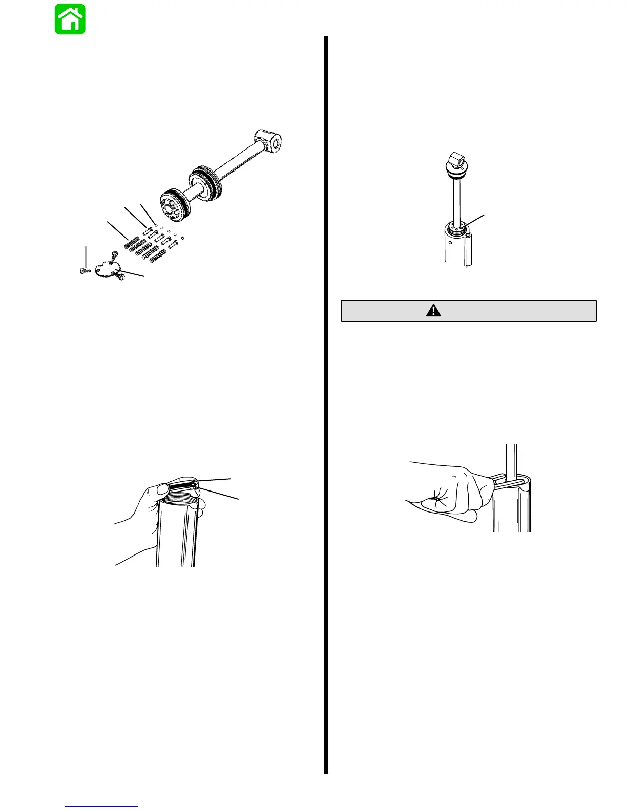
4. Install shock rod into cylinder until power trim fluid
flows through oil blow off ball passage. Fill re-
maining cylinder to just below the cylinder
threads.
a
a - Oil Blow Off Ball Passage
CAUTION
End cap must not make contact with shock rod
piston when tightening. Shock rod piston must
be positioned in cylinder deep enough to avoid
contact.
5. Tighten end cap securely using spanner wrench
[1/4 in. x 5/16 in. (6.4mm x 8mm) long pegs].. If
a torquing type spanner tool is used to tighten end
cap, then torque to 45 lb. ft. (61.0 N·m).