2A-26 - ELECTRICAL 90-830234R3 DECEMBER 1997
RED Stator with CDM
Ignition Component Description
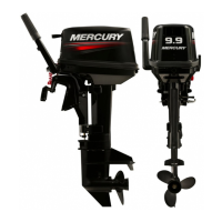
CAPACITOR DISCHARGE MODULE (CDM)
Each module contains an ignition coil and amplifier
circuitry which produces approximately 45,000 volts
at the spark plugs.
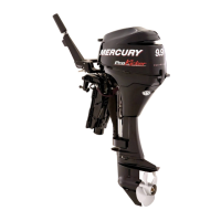
TRIGGER COIL
Located under flywheel. Is charged by single magnet
on flywheel hub. Trigger pulses are sent to CDM.
STATOR ASSEMBLY
Located under the flywheel in the stator assembly are
12 coils (6 for manual stator), 3 ignition charge coils
and 9 auxiliary(3 for manual) power coils wound in
series that provide voltage to the CDM’s and battery/
auxiliary circuits respectively.
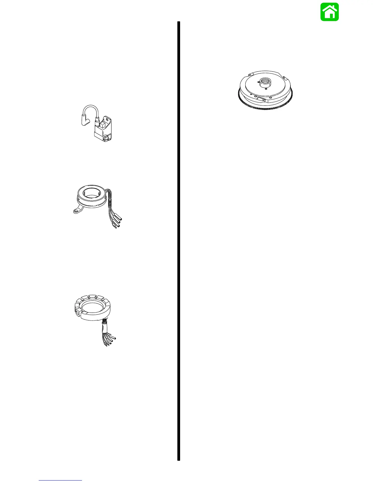
FLYWHEEL
Contains 6 magnets (12 pole) around circumference.
Has one magnet on inner hub for trigger. Outer mag-
nets are for battery charge coils and ignition charge
coils.
NOTE: Electric start model flywheel shown.
IMPORTANT: Before replacing ignition compo-
nents:
1. Verify plug-in connectors are fully en-
gaged.
2. Check that electrical components are
grounded to ignition plate and that igni-
tion plate is grounded to cylinder block.
3. Check for open or short circuits in wiring
harness.