90-830234R3 DECEMBER 1997 POWERHEAD - 4-37
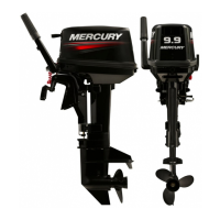
• Crankshaft may be removed as an assembly, or
by component parts.
IMPORTANT: Rod caps MUST be reassembled on
the same rod - in the same direction. Re-bolt cap
to rod immediately or mark rods and caps.
a
19314
a - Main Bearings
• Remove main roller bearing assemblies (2) from
crankshaft as follows;
• Remove retaining ring.
• Remove race.
• Remove main roller bearings.
a
b
c
a
c
27649
a - Retaining Ring
b - Race
c - Main Roller Bearings
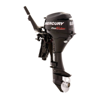
• Remove 2 bolts, each rod cap, using a 3/8″, 12
point socket.
IMPORTANT: Before disassembly, use a carbide-
tip scriber to mark caps and rods, to return pis-
tons to proper cylinder.
• Remove piston assembly from crankshaft; reat-
tach caps to respective rods, as each is removed.
CAPS MUST BE INSTALLED IN SAME DIREC-
TION ON SAME ROD, or mating surfaces will not
seat properly.
a
19328
a - Bolts
IMPORTANT: BOTH the piston rod and rod cap
bolt holes are threaded. The rod cap and rod
must be aligned and held tight together when
threading in rod cap bolts. Check mating sur-
faces to be sure that they are tight together after
bolt enters the threads in the piston rod.
• Remove main bearing sealing rings - 2 per center
main journal.
51083
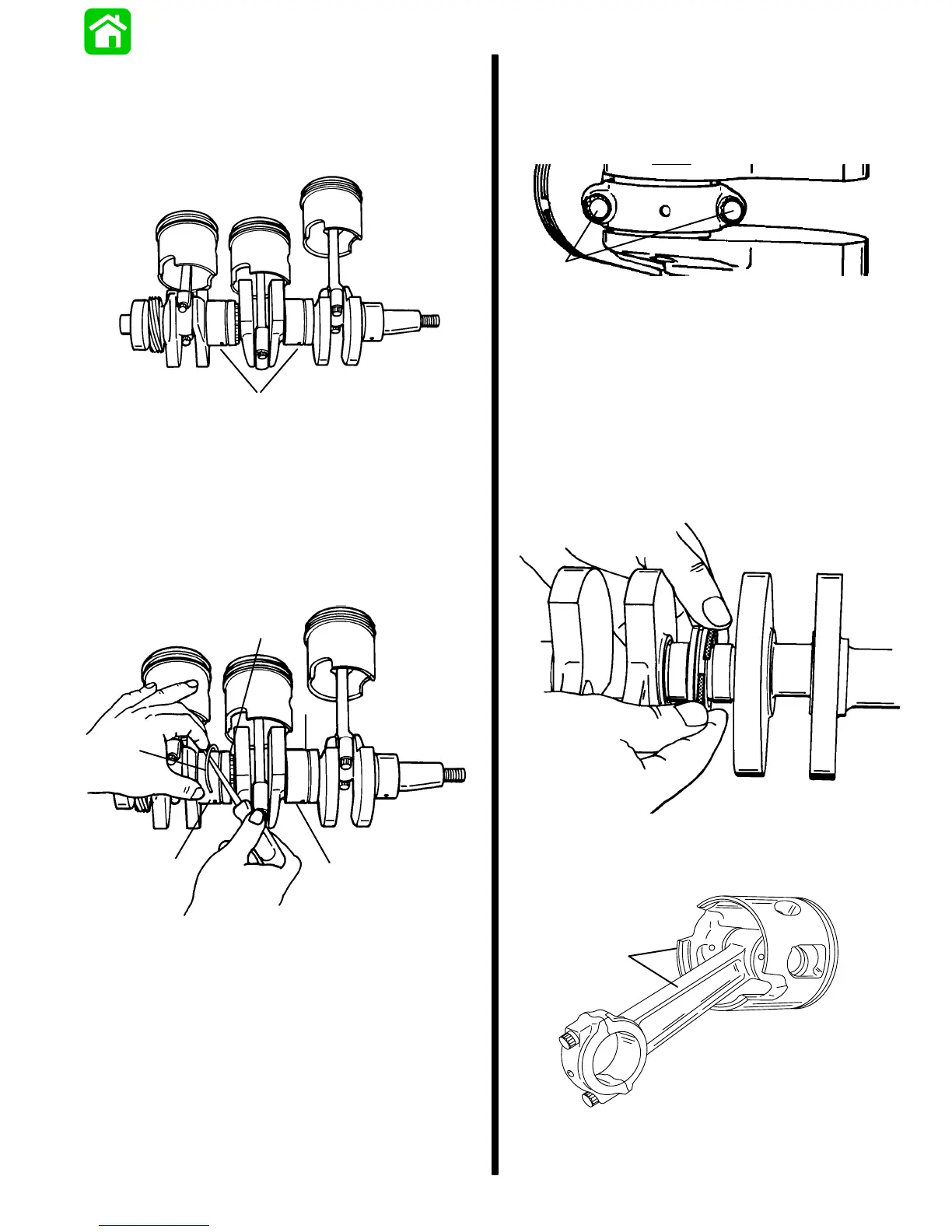
• Using an awl, scribe identification number of con-
necting rod on inside of piston. Reassemble pis-
ton on same connecting rod.
a
53985
a - Scribe Mark