6A-28 - LOWER UNIT 90-830234R3 DECEMBER 1997
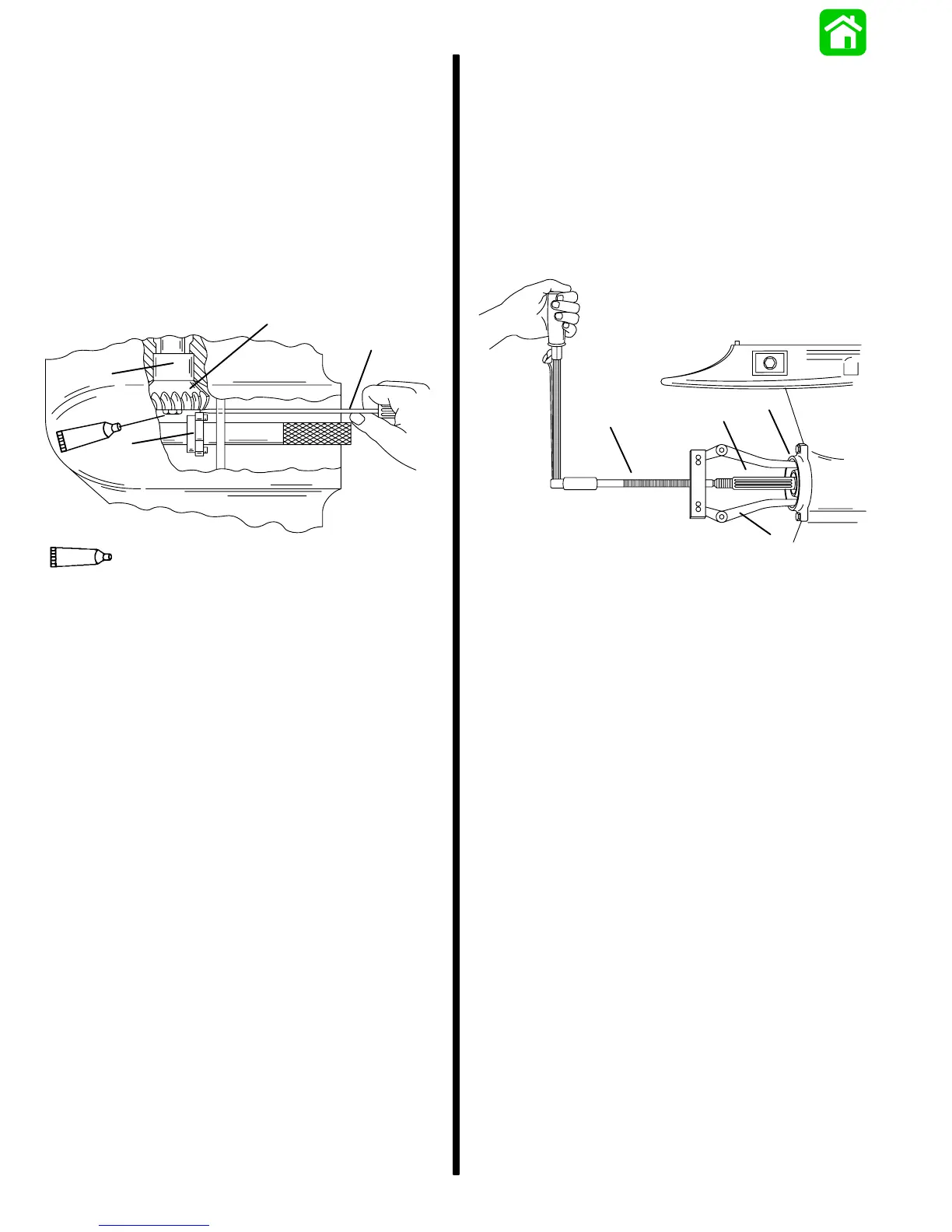
12. Determine pinion gear depth by inserting a feeler
gauge thru access hole in locating disc.
13. The correct clearance between gauging block
and pinion gear is 0.025 in. (0.64mm).
14. If clearance is correct, leave Bearing Preload
Tool on drive shaft and proceed to “Determining
Forward Gear Backlash,” following.
15. If clearance is incorrect, add (or subtract) shims
from above bearing race to lower (or raise) pinion
gear. When reinstalling pinion nut, apply Loctite
271 on threads of nut.
a
c
d
b
24643
7
Loctite 271 (92-809820)
7
a - Feeler Gauge
b - Gauging Block
c - Pinion Gear
d - Bearing Race
DETERMINING FORWARD GEAR BACKLASH
NOTE: Read entire procedure before attempting any
change in shim thickness.
1. Obtain correct pinion gear depth; refer to “Deter-
mining Pinion Gear Depth,” preceding.
2. Install Bearing Preload Tool (91-14311A2) on
drive shaft; refer to “Determining Pinion Gear
Depth,” preceding.
3. Install components as shown.
d
a
b
c
53936
a - Propeller Shaft*
b - Bearing Carrier* (Assembled)
c - Puller Jaws (91-46086A1)
d - Puller Bolt (91-85716); Torque to 45 lbs. in. (5.1 N·m)
* Refer to “Bearing Carrier and Propeller Shaft Installation,”
following.
4. Rotate drive shaft 5 to 10 revolutions. This should
properly seat forward gear tapered roller bearing.

 Loading...


