90-830234R3 DECEMBER 1997 ATTACHMENTS/CONTROL LINKAGE - 7A-9
c. Insert ends of steering cables thru engine tilt
tube and cable mounting tube (Figure 3).
Thread steering cable attaching nuts hand-
tight onto tubes.
b
a
e
f
d
c
c
d
f
e
b
a
50101
a - Flat Washer (2 Each Link Rod)
b - Nylon Insert Locknut - Torque Until it Seats [DO NOT Ex-
ceed 120 lb. in. (13.6 Nm) of Torque], then Back Off
1/4-Turn
c - Special Washer Head Bolt (10-14000) - Torque to 20 lb. ft.
(27.0 Nm)
d - Nylon Insert Locknut - Torque to 20 lb. ft. (27.0 Nm)
e - Steering Link Rod
f - Steering Cable End
Figure 3. Steering Cables and Link Rod Installed
NOTE: Torque steering cables’ attaching nuts and
install locking sleeves after final tension adjustment.
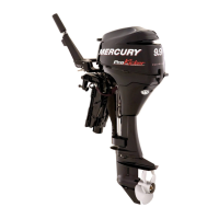
5. Install steering cable seal to steering cable
mounting tube, as follows:
a. Place a mark on steering cable mounting
tube 5/8″ (16mm) from end of tube (Figure 4).
b
a
cd
e
50180
a - 5/8″ from End of Tube
b - Place Mark on Tube Here.
c - Nylon Spacer
d - O-ring
e - Cap
Figure 4. Seal Installation Sequence
a
50180
a - Mark Made in Step 5a
Figure 5. Steering Cable Seal Installed
b. Slide plastic spacer, O-ring and cap (from kit)
over steering cable (Figure 4).
c. Thread cap onto steering cable mounting
tube up to mark [made on tube in Step “a”
(Figure 5)].
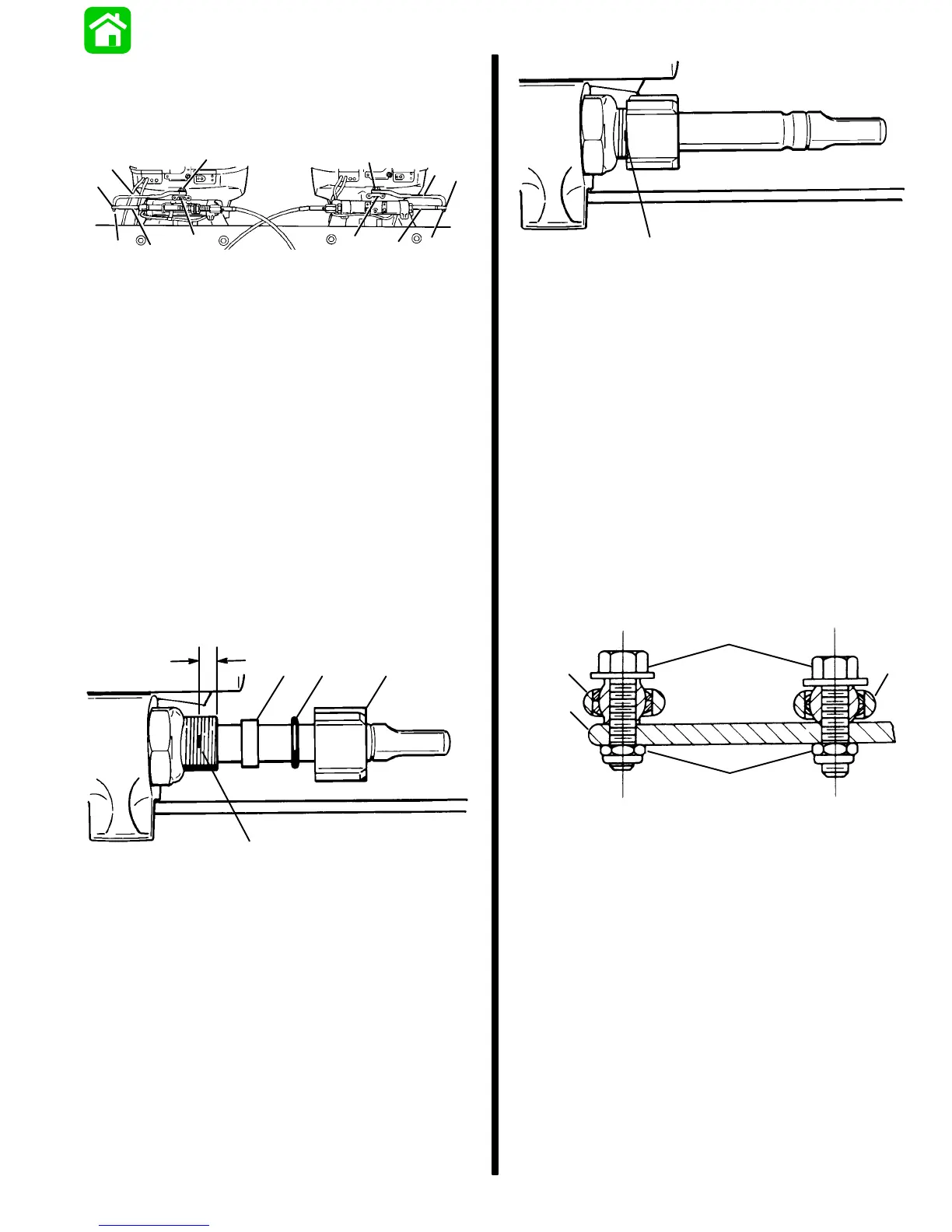
6. Install link rods (supplied with engines) to engine
steering arms (Figure 3). Fasten each link rod to
steering arm onto topside rear hole with pivot bolt
and locknut, as shown in Figure 6. Torque each
pivot bolt to 20 lbs. ft. (27.0 Nm), then thread
locknut onto pivot bolt and torque nut to 20 lbs. ft.
(27.0 Nm).
d
e
b
c
a
a - Engine Steering Arm
b - Steering Link Rod
c - Steering Eye and Coupler
d - Pivot Bolts - Torque to 20 lbs. ft. (27.0 Nm)
e - Locknuts - Torque to 20 lbs. ft. (27.0 Nm)
Figure 6. Steering Link Rod and Steering Eye
with Coupler Installed on Engine Steering Arm
 Loading...