2B-8 - ELECTRICAL 90-830234R3 DECEMBER 1997
6. Remove RED sense lead wire (A) from starter so-
lenoid terminal and connect to the positive (+) ter-
minal of a 9 volt transistor battery. Ground the
negative (–) terminal of the 9 volt battery to the
engine.
a
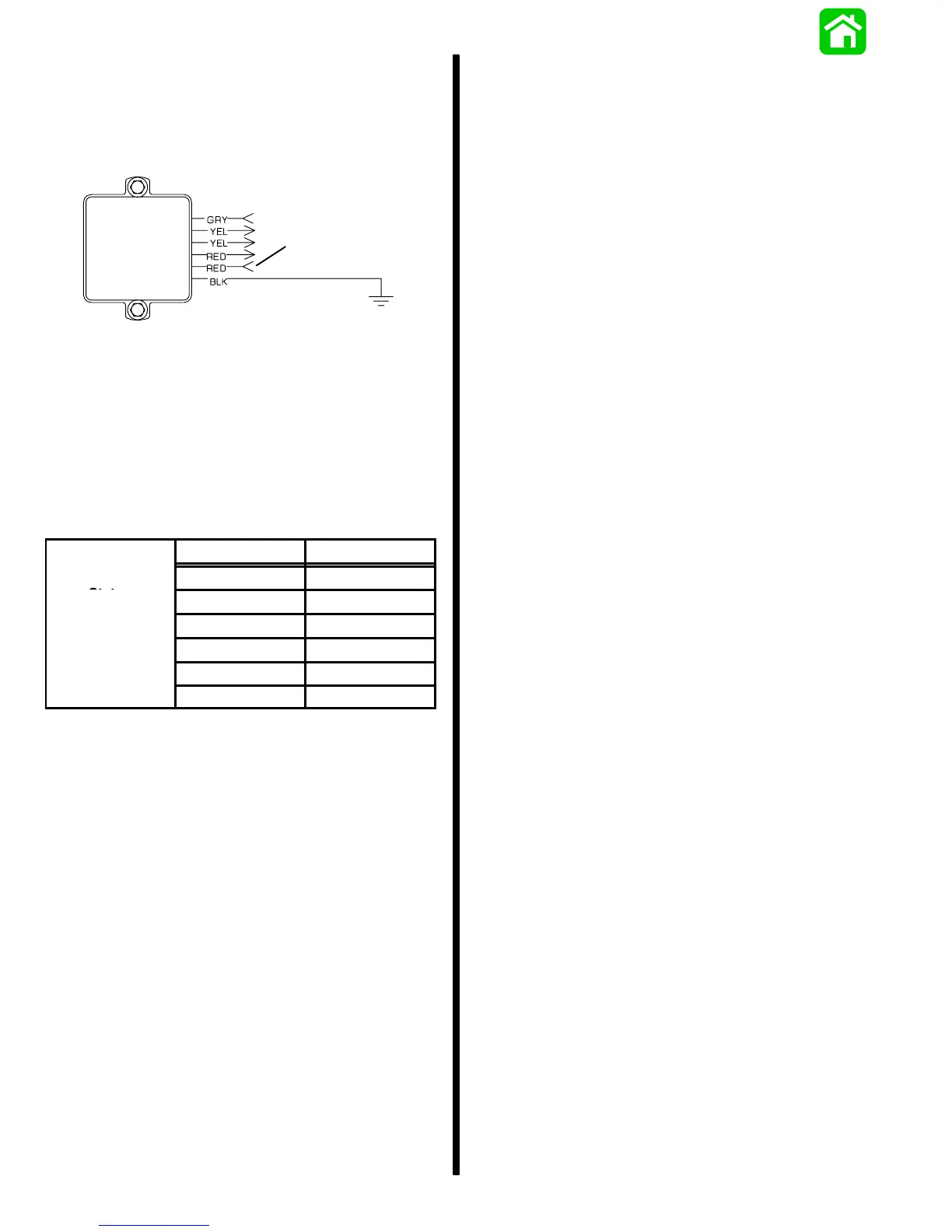
a - Red Sense Lead (Female Connector)
7. Connect RED (+) ammeter lead to larger diame-
ter RED harness wire, and BLACK (–) ammeter
lead to POSITIVE terminal on starter solenoid.
8. Secure starter wires away from flywheel.
9. With engine running at the indicated RPM’s, the
ammeter should indicate the following approxi-
mate amperes:
RPM AMPERES
16 Ampere
Idle 2.8
Stator
1000 9.3
2000 16.0
3000 17.0
4000 17.5
5000 17.5
10. A reading of 16 amperes at 2000 RPM indicates
the charging system is functioning properly. The
battery is being discharged because of the
excessive amperage draw on the system (the
draw is greater than the amperage output of the
engine charging system).
11. If ammeter reads less than required amperes @
3000 RPM, test the stator; refer to “Stator Ohm
Test (Alternator Coils Only)”. If stator tests OK,
replace voltage regulator.